Showing posts with label fiber optic coupler. Show all posts

Tuesday, December 10, 2013

Comparation Between EPON and GPON


With the continuous progress of science and technology, the Internet has gradually gone into the homes of the ordinary people, and the speed of broadband has increasingly become the topic of people in the entertainment and work often, from narrowband dial-up to broadband Internet, and then the fiber access Internet, broadband network, the rapid pace of PON technology gradually come to the front. Currently, there are two quite compelling PON standard has been officially released, which are GPON standard developed by the ITU / FSAN and EPON standard developed by IEEE 802.3ah working group. PON technology has been no doubt the ultimate solution for the future FTTH era. EPON and GPON who will the dominant FTTH tide has become a new hot debate. What's the difference between EPON and GPON?
GPON and EPON Differences
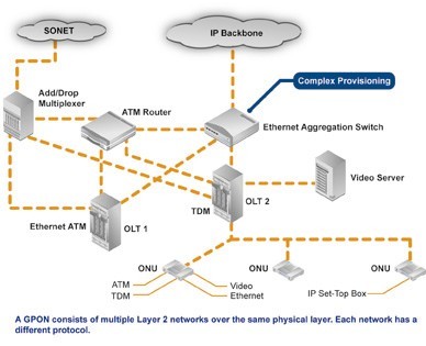
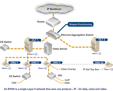
Perhaps the most dramatic distinction between the two protocols is a marked difference in architectural approach. GPON provides three Layer 2 networks: ATM for voice, Ethernet for data, and proprietary encapsulation for voice. EPON, on the other hand, employs a single Layer 2 network that uses IP to carry data, voice, and video.
A multiprotocol transport solution supports the GPON structure (Figure 1). Using ATM technology, virtual circuits are provisioned for different types of services sent from a central office location primarily to business end users. This type of transport provides high-quality service, but involves significant overhead because virtual circuits need to be provisioned for each type of service. Additionally, GPON equipment requires multiple protocol conversions, segmentation and reassembly (SAR), virtual channel (VC) termination and point-to-point protocol (PPP).
Figure 1: Diagram showing a typical GPON network.
EPON provides seamless connectivity for any type of IP-based or other "packetized" "communications" (Figure 2). Since Ethernet devices are ubiquitous from the home network all the way through to regional, national and worldwide backbone networks, implementation of EPONs can be highly cost-effective. Furthermore, based on continuing advances in the transfer rate of Ethernet-based transport — now up to 10 Gigabit Ethernet — EPON service levels for customers are scalable from T1 (1.5 Mbit/s) up through 1 Gbit/s.
Figure 2: Diagram showing a typical EPON network.
Upstream Bandwidth
Subtracting the various system run overhead from the total bandwidth of the system uplink transmission is the upstream available bandwidth. It has a great relationship with the number of the ONU contained in the system, DBA (Dynamic Bandwidth Allocation) algorithm polling cycle, the type of bearer services, as well as the various business proportion. EPON and GPON are broadband access technology, hosted business IP data services. Below we will calculate the uplink the beared pure IP services available bandwidth of EPON and GPON that contain 32 ONUs, fiber optic coupler,the case of polling period 750s.
EPON
EPON upstream rate is 1.25 Gbit/s. Because the 8B/10B line coding, each 10bit are 8bit valid data, so its effective upstream transmission bandwidth is 1 Gbit/s. EPON upstream overhead of running the system and its proportion of the total bandwidth are as following:
1. Used for the the burst reception of physical layer overhead: about 3.5%;
2. Ethernet frame encapsulation overhead: about 7.4%;
3. MPCP (Multi-Point Control Protocol) and OAM operation and management of maintenance protocol overhead: about 2.9%;
4. DBA algorithm resulting in the remaining time slots (that is not sufficient to transfer a complete Ethernet frame time slot) wasted: about 0.6%;
5. EPON upstream total overhead is all of the above about 144 Mbit/s, the available bandwidth is about 856 Mbit/s.
GPON
GPON supports a variety of rate levels, has asymmetric rate that downlink is 2.5Gbps or 1.25Gbps, the upgoing is 1.25Gbps or 622 Mbps. NRZ encoding the uplink total bandwidth for 1.244 Gbit/s, GPON upstream overhead of running the system as following:
1. The proportion of its total bandwidth is used for the the burst reception of physical layer overhead: about 2.0%;
2. GEM (GPON encapsulation method) frame and the Ethernet frame encapsulation overhead: about 5.8%;
3. The PLOAM (physical layer operation, management and maintenance) protocol overhead: about 2.1%;
4. Remaining slots of the DBA algorithm introduced the additional encapsulation overhead: about 0.8%.
5. GPON upstream total overhead is all of the above about 133 Mbit/s, the available bandwidth about 1111 Mbit/s.

Friday, September 6, 2013

40/100GbE MPO FIBER OPTIC CONNECTOR – NORTH AMERICA MARKET FORECAST


According to ElectroniCast, 12-fiber single mode MPO connector consumption value will increase 141% per year through 2016…
ElectroniCast Consultants, a leading market research & technology forecast consultancy addressing the fiber optics communications industry, today announced the release of their annual market forecast of the North American consumption of MPO Fiber Optic Connectors used in 40 and 100GbE communication links.
In 2006, the IEEE 802.3 working group formed the Higher Speed Study Group (HSSG) and found that the growth in bandwidth for network aggregation applications was outpacing the capabilities of networks employing link aggregation with 10 Gigabit Ethernet. (The standard was announced in July 2007 and was ratified on June 17, 2010).
Applications such as video, virtualization (cloud computing), switching/routing and convergence are driving the need for bandwidth expansion. We continue on the path of gradually developing of growth (and change) from 1G to 10G to 40G and 100G. For data center (DC) environments operating at 40GbE or 100GbE, fiber optic cabling is generally recommended because its reach supports a wider range of deployment configurations compared to copper solutions.
The capability to choose increased speed will enable networks to play with the 10GbE resources to the access layer allowing 40/100GbE to handle traffic at the aggregation and core layers. In this market research report, ElectroniCast Consultants provides their 2011-2016 forecast and analysis of MPO fiber optic connectors used in North American 40/100GbE optical communication networks.
The 10GbE movement into the data centers will continue; however, “future-proofing” is continuing with an accent (40/100G), which is driven by significant broadband expansion demands, especially in regards to network productivity and operating expenses (OPEX costs).
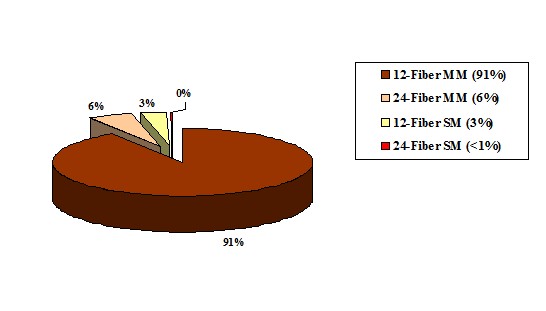
According to ElectroniCast, 12-fiber multimode MPO patchcord dominate the North American (Mexico, Canada and the United States) 40/100GbE MPO connector marketplace in 2012; however, 12-fiber single mode MPO connector consumption value will increase at the fastest pace of 141% per year through 2016.
According to ElectroniCast, 12-fiber multimode MPO connectors currently dominate the North American 40/100GbE MPO connector marketplace, based on consumption value…
40 and 100 GbE MPO Connector Value

North America Market Share (%) in 2012, by Type

mpo patchcord
(Source: ElectroniCast Consultants)
DK Photonicswww.dkphotonics.com specializes in designing and manufacturing of high quality optical passive components mainly for telecommunication, fiber sensor and fiber laser applications,such as PLC Splitter, WDM, FWDM, CWDM, DWDM, OADM, Circulator, Isolator, PM Circulator, PM Isolator, Fused Coupler, Fused WDM, Collimator, Optical Switch and Polarization Maintaining Components, Pump Combiner, High power isolator, Patch Cord and all kinds of connectors.

Wednesday, May 15, 2013

Basics of fiber optic networks

Hello again dear friends! Before that, we mostly discussed with you issues related to communications systems to transmit signals using electrical impulses, and now it is time to talk about another type of communication systems based on the use of optical pulses - fiber optic communication systems.

Existing communication systems that move data over copper, nice to everyone, except the distance to which they can transmit information (without intermediate amplification of points) is pretty limited. This eliminates the drawback  of fiber-optic transmission systems.

As probably not hard to guess all the usual copper communication cables are not suitable for optical signal transmission. Therefore, the fiber-optic networks used by another type of cable - optical cables. Outside (outer shell), these cables are similar to conventional copper cables (although there are some differences), but inside they contain are not familiar copper wires and optical fibers specially designed for the transmission of optical pulses. Typically, optical fibers made of quartz glass or certain types of plastic and have the following structure:
Design of optical fiber
As seen from the figure, the optical fiber is composed of two parts: the core and the shell. The core and the shell made of the characteristics of different materials, with consideration to the refractive index of the core was slightly higher than the refractive index of the shell. With such a ratio of the refractive indices, the light beam entering the core of the optical fiber, will be distributed by him due to the effect of total internal reflection occurs at the boundary between two media (the core and the cladding of an optical fiber).

By themselves, the optical fibers are relatively fragile, so they are covered by a special membrane buffer, and then combined in the optical modules, which are covered from above with additional protective layers. In general, the design of optical cable can be as follows (but in fact it may be different):
The design of an optical cable
For the introduction of an optical signal into an optical cable (and thus taking it to the other side of the cable) are special optical transceivers, which in practice is usually built into SFP modules are designed for installation in a variety of network devices, or directly in the optical device ports.
Skin and SFP modules
Consider how the direct connection of multiple network devices using fiber optics. Suppose we have two switches with connectors for SFP modules (if there is no switch with a socket for the SFP modules, you can use the circuit switch - media converter).
Switch with SFP connectors to install modules
In the SFP ports on the switch are installed SFP modules. Specific model SFP modules selected based on design requirements (required transmission distance, the type of optical cable, etc.).
Installing SFP Modules
For connectors installed SFP modules are connected optical patch cords (actually too optic cable, but containing only 1 or 2 fibers, and having a simple structure), the other end of the optical patch cords are connected to the terminals of optical distribution frame. Optical patch cords may have different optical connectors at its ends, the choice of a particular model (with certain connectors) is determined by optical connectors SFP modules and connectors optical distribution frame.
The appearance of the optical patch cord
Optical Distribution Frame roughly represents a metal box with connectors, which are connected outside optic patch cords and pigtails in (generally half the optical patch cord, used for okontsovyvaniya trunk optical cable). Also located inside the optical cross special cassettes and apparatus for fixing cables.
The appearance of the optical coupler
On the other side of the optical cross comes backbone fiber optic cable that will connect two remote sites.
The principle of operation of optical distribution frame
If you collect the whole scheme together, it will look like the following:
Connecting two remote sites using fiber-optic network
That's pretty hard not possible to connect two remote sites using the means of fiber-optic communications.

Friday, May 10, 2013

What Is A Fiber Optic Adapter?


Fiber optic adapter, also called Fiber Optic Coupler, is a small device that used to terminate or link the fiber optic cables or fiber optic connectors between two fiber optic lines. A Fiber Adapter allows fiber-optic cables to be attached to each other singly or in a large network, allowing many devices to communicate at once. Fiber Optic Adapters are widely used in light distribution frame(ODF), optical fiber communications equipment, measuring appliance and so on.
Features
Optical adapter comes in versions to connect single fibers together (simplex), two fibers together (duplex), or sometimes four fibers together (quad).
Most adapters are female on both ends, to connect two cables. Connecting two cables together can allow two devices to communicate from a distance through a direct connection with the fiber optic line. Some are male-female, which typically plug into a port on a piece of equipment. This then allows the port to accept a different connector than for which it was originally designed. We discourage this use because we find the adapter extending from the equipment is subject to being bumped and breaking. Also, if not properly routed, the weight of the cable and connector hanging from the adapter may cause some misalignment and a degraded signal.
Function
Fiber optic adapters are typically connecting cables with similiar connectors (SC adapter to SC connector, LC adapter to LC Connector, etc.). Some adapters, called “hybrid”, accept different types of connectors (ST to SC, LC to SC, etc.). When attempting to connect two cables that are different shapes, it is necessary to use a hybrid connector.
There are also adapters that can be used to attach a bare fiber-optic cable to a Power Adapter. This piece allows the cable to fit into a connection slot, whether into a mating sleeve or into an electronic device. The fiber-optic cable can be fit into an adapter that works with any of the standard shaped connectors.
Types
The fiber optic adapters are many types because of the diversity of the connectors. In order to realize the fluent fiber optic connection, the fiber optic adapter panel shapes or types should be in accordance with the fiber optic connectors or cables. Common shapes of the adapters are square, rectangular, or round that with FC, LC, ST, SC, MTRJ types. These simple types of adapters are often referred to as mating sleeves because they allow two cables to connect to one another. Some of these common line to line connectors are also built to connect three or four cables together.
There are also single mode and multimode fiber optic adapters or single mode and multimode fiber optic connections. They are designed for singlemode or multimode cables. The singlemode adapters offer more precise alignment of the tips of the connectors (ferrules). It is ok to use singlemode adapters to connect multimode cables, but you should not use multimode adapters to connect singlemode cables. This can cause misalignment of the small singlemode fibers and loss of signal strength (attenuation).
Flange fiber optic adapters are typically with ceramic sleeves, fitting for both single mode and multimode fiber optic connector. The adapters are in many different shapes, but they all serve the same purpose.
PCI Network Adapter acts as the interface between a computer and a fiber optic network cable. The purpose of the fiber optic network card is to prepare, send, and control data on the network. There are 100M, 1000M, and 10G fiber optic network card adapter available. Fiber network interface cards are available in both Multimode and Single-mode configurations with ST, SC, MTRJ, orLC connectors, and SFP for Gigabit.
Because the fiber adapters should fit the according connectors, the fiber optic adaptors sides and shape are made as per the connectors. Generally, ST adapter and FC adapter are metal body, LC, SC, MU, MTRJ, E2000 types are non-metal body. Single mode fiber optic adapters are with ceramic sleeves, multimode fiber optic adapters are bronze sleeves. But you can also use ceramic sleeve fiber optic adapters to link multimode connectors.

Wednesday, May 8, 2013

Fiber optic patch cord|fiber optic pigtail|optical connector|fiber optic adapter-DKComm

Fiber optic patch cord|fiber optic pigtail|optical connector|fiber optic adapter-DKComm
DKComm Technology Co.,Limited was founded by a leading team of professional technicians and research pioneers, who have been dedicated to the fiber optic communication sector for years. DKComm main products include fiber optic patch cord, fiber optic pigtail, fiber optic connector, fiber optic adapter, fiber optic attenuator, fiber optic coupler, fiber optic splitter, fiber optic splice closure, Fiber Optic Termination Box, ODF etc, which are widely used in telecommunications system, LAN, CATV and network industry.

Tuesday, May 7, 2013

1X4 Monolithic Single Mode Coupler_Optical coupler_DK Photonics

1X4 Monolithic Single Mode Coupler_Optical coupler_DK Photonics

1X4 monolithic couplers(The Single Mode Single Fusion Coupler) have the compact package size, low insertion loss, and high reliability performance. These couplers were designed for optical modules and the fiber sensors, fiber testing instruments.

Monday, May 6, 2013

When Do We Need Fiber Optic Splicing


When we want two fibers or fiber optic cables joint together, there are two method come to our head, installing a fiber optic connectors at the end of the optical fibers, or splicing the two optical fibers. Fiber optic cable splicing is a method that creates a permanent joint for two fibers, while fiber connector installation is used for temporary connections. There are two options for fiber optic splicing: Fiber optic cable fusion splicing and mechanical splicing. Both methods provide much lower insert loss than fiber optic connectors.
Common application for splicing is jointing cables in long outside plant cable runs where the length of the run requires more than one cable. Splicing is generally used to terminate singlemode fibers by splicing preterminated pigtails onto each fiber. It can be also used to mix numbers of different types of fiber cables like connecting a 48 fiber cables to six 8 fiber cables going to different places.
Fusion splicing provides a maximum insertion loss of 0.1 which is less than 0.5dB of mechanical splicing. Fusion splicer are available in two types that splice a single fiber or a ribbon of 12 fibers at one time. Almost all singlemode splices are fusion spliced. Mechanical splicing is most used for temporary restoration and for multimode splicing. Fusion splices are so good today that splice points may not be detectable in OTDR traces.
Fusion Splicing Process
Fusion splices are made by welding two fibers together by an electric arc of the fusion splicing machine. It can be not done in the enclosed space for safety reasons. It is suggested to done the job above the ground in a truck or trailer for a clean environment for splicing.
Fusion splicing needs the help of a special equipments which is fusion splicer to perform the splicing process. Main steps are aligning the two fibers precisely and generate a small electric arc to melt the fibers and weld them together.Splicing machine can do one fiber at a time while mass fusion splicer can do all 12 fibers in a ribbon at once.
Preparing fibers: The first step for fusion splicing is to strip, clean & cleave the fibers to be spliced. Stripping the primary buffer coating to expose the proper length of bare fiber with the fiber stripper. Clean the fiber with appropriate wipes, what you need is the fiber optic cleaning kit, Cleave the fiber using the directions appropriate to the fiber cleaver being used. Place each fiber into the guides in the fusion splicing machine and clamp it in place.
Running the splicer program: Choose the proper program according to the fiber type being spliced. The splicer would show the fibers being spliced on a video screen. The fiber ends will be inspected for proper cleavers and bad ones will be rejected for a second time cleaving. The fibers will be moved into position, prefused to remove any dirt on the fiber ends and preheat the fibers for splicing. The fibers will be aligned using the core alignment method used on that splicer. Then the fibers will be fused by an automatic arc cycle that heats them in an electric arc and feeds the
fibers together at a controlled rate.
Ribbon fusion splicing: Each ribbon is stripped, cleaved and spliced as a unit. Special tools are needed to strip the fiber ribbon, usually heating it first, then cleave all fibers at once. Many tools place the ribbon in a carrier that supports and aligns it through stripping, cleaving and splicing. Consult both cable and splicer manufacturers to ensure you have the proper directions.
Fusion splicing pigtail is another typical application for fiber optic splicing. By this method, a fiber optic patch cord is cut into two pigtails with connectors attached. The fibers are cleaved and welded together with a fusion splicer, which is considered to be the fastest and highest-quality method of fiber connector installation.

Sunday, April 21, 2013

What Is an Optical Attenuator?

An optical attenuator decreases the strength of an optical signal passing through it to a fiber optic cable or open air. The intensity of the signal is described in decibels over a specific distance the signal travels. It is the strength, or amplitude of the signal that changes and not the overall waveform or frequency, so the optical signal remains undistorted for use in the desired application. Optical attenuators are often used in optical communication systems, in which the attenuation, also called transmission loss, helps with the long-distance transmission of digital signals. The most common optical attenuator types include fixed and continuously variable attenuators.
Often installed where signals are transmitted from, an optical attenuator can apply the principle of gap loss so the signal intensity is lowered to the optimal level over a given distance. Attenuators installed elsewhere along the optical fiber will not lower the signal strength enough, but some devices utilize signal absorbing or reflecting components to compensate. An optical fiber connector is often attached to the optical attenuator which typically has an adapter with a female configuration. The attenuator itself usually has a cylindrical or even box-like structural shape which determines the type of equipment in which it can be installed.
The fixed variety of optical attenuator, sometimes found in an electronic circuit, does not reflect light signals to reduce their intensity. It is generally used where the transmission of data needs to be highly accurate. The device’s function is determined by the amount of power it can handle in addition to important variables such as performance versus temperature and frequency range. Most optical attenuators utilize resistors, but a variable optical attenuator uses metal semiconductor field effect transistors or other solid state components. Attenuation intensity is adjustable so the signals in a fiber optic communication system can be changed to accommodate fluctuating power levels, protecting the system from damage.
A variable optical attenuator can be mounted on a printed circuit board, or used in test devices such as an optical power meter. Many attenuators are installed in-line with an optical fiber cable in order to adjust the transmitted signal accordingly. They are sold by many retailers and manufacturers online so one can assess their characteristics by reading the product specifications. Aspects to consider include the average and peak power the device can tolerate, how much attenuation it provides, as well as its overall dimensions and the type of environment it can operate in.

Thursday, March 21, 2013

Relationship Between The Optical Coupler And PLC Splitter


In fact, splitter is named for the function of the device, coulper named for its working principle, splitter may be based coupler, and may be based on the waveguide or the separating element, coupler can be done either the splitter, but also can be done WDM, attenuator.

Optical coupler either split optical signals into multiple paths or combines multiple signals on one path. Optical signals are more complex than electrical signals, making optical couplers trickier to design than their electrical counterparts. Like electrical currents, a flow of signal carriers, in this case photons, comprise the optical signal. However, an optical signal does not flow through the receiver to the ground. Rather, at the receiver, a detector absorbs the signal flow. Multiple receivers, connected in a series, would receive no signal past the first receiver which would absorb the entire signal. Thus, multiple parallel optical output ports must divide the signal between the ports, reducing its magnitude. The number of input and output ports, expressed as an N x M configuration, characterizes a coupler. The letter N represents the number of input fibers, and M represents the number of output fibers. Fused couplers can be made in any configuration, but they commonly use multiples of two (2 x 2, 4 x 4, 8 x 8, etc.).

PLC Splitter is a device that split the fiber optic light into several parts by a certain ratio. The simplest couplers are PLC Splitters. These devices possess at least three ports but may have more than 32 for more complex devices.PLC Splitters are important passive components used in FTTX networks. But two kinds of fiber splitters are popular used, one is the traditional fused type PLC Splitter (FBT splitter), which features competitive prices; the other is PLC PLC Splitter, which is compact size and suit for density applications. Both of them have its advantages to suit for different requirement.

PLC Splitter typical parameter include input and output part cable length, splitting ratio, working wavelength and with what kind of fiber optic connectors. Just like fiber patch cable, fiber splitters are usually with 0.9mm, 2mm or 3mm cables. 0.9mm outer diameter cable is mostly used in stainless steel tube package PLC Splitters, while 2mm and 3mm cables are mostly used in box type package fiber splitters. Based on working wavelength difference there are single window and dual window PLC Splitters. And there are single mode fiber splitter and multimode fiber splitter. Typical connectors installed on the PLC Splitters are FC or SC type.

Optical coupler or PLC splitters are available in a selection of styles and sizes to separate or combine light with minimal loss. All couplers are produced employing a proprietary procedure that produces reliable, low-cost devices. They’re rugged and impervious to common high operating temperatures. Couplers can be fabricated with custom fiber lengths or with terminations of any type.