Showing posts with label optical coupler. Show all posts

Thursday, October 29, 2015

Work Theory of the Laser Cutting Machine(2)

Cutting methods of laser cutting machine

Vaporization cutting
It means that vaporization is the main way to remove the processed material. In the process of vaporization cutting, workpiece surface is heated to vaporization temperature quickly by focused laser beams, forming High pressure steam and spraying outward at supersonic speeds. In the meantime, a hole is formed in the laser active area and laser beams reflex several times in the hole to increase the absorption of laser pump power combiner by material.
When high-pressure vapors spray outward, the melted materials are blown away in the kerf till the workpiece is finally cut. Vaporization cutting needs very high power density, which is eighth power of ten watt above per square centimeter. It is usually applied in low flash point materials and refractory materials.
Reaction Fusion Cutting
When assistant airflow not only blows the melted materials from the kerf but also has thermal reaction with the workpiece, this is the so-called reaction fusion cutting. Gases that can have reaction with workpiece are oxygen or mixture gases containing oxygen. When the surface  temperature of workpiece reach to ignition temperature, strong combustion heat release occurs to improve the laser cutting ability.
Combustion heat release of low carbon steel and stainless steel is 60%. And it is about 90% for reactive metals like titanium.
Compared to vaporization cutting and general fusion cutting, reaction fusion cutting need less laser power density. However, reaction fusion cutting may effect the performance of worpiece since the combustion reaction can lead to chemical reaction on materials.
Fusion Cutting
When adding a assistant airflow system coaxial with laser to  blow the melted materials away from kerf, this kind of cutting is fusion cutting. In fusion fiber coupler cutting, workpiece needn't to be heated to vaporization temperature so the required laser power density is reduced greatly.
Laser Scribing
It is mainly used in semiconductor materials, in which laser of high power density make a shallow groove in the semiconductor materials of the workpiece and then makes it crack through mechanistic or vibratory methods. The quality is valued by the surface fragments and size of heat affect area.
Cold Chipping
It is a new processing method, which is put forward along with ultraviolet band superpower excimer laser appeared in recent years. The basic theory is that energy of ultraviolet photons is similar to binding energy of many organic materials; this high-energy photons are used to impact bond organic materials thus make it crack, achieving purpose of cutting. This new technology has promising application future, especially in electron industry.
Thermal Stress Cutting
Mechanism of thermal stress cutting is that laser beams heat an area of fragile material to produce evident temperature gradient. The high surface temperature makes expansion and inner lower temperature hinders expansion, forming pulling stress in the surface and radial crushing stress inside. When the two stresses exceed fracture limit strength of the workpiece, crackle appears. And then the workpiece is broken along the normal direction of the crack. It is suitable for glasses and ceramics.
Conclusion: laser cutting machine is a cutting technology of melting and gasifying surface material through focused energy generated by the use of laser specialties and focused lens. It features good cutting quality, high speed, various cutting material and high efficiency.
About DK Photonics
DK Photonics – www.dkphotonics.com  specializes in designing and manufacturing of high quality optical passive components mainly for fiber laser applications such as 1064nm high power isolator, Cladding Power Stripper, Multimode High Power Isolator, pump combiner,1064nm Band-pass Filter,(6+1)X1 Pump and Signal Combiner, PM Circulator, PM Isolator, optical Coupler. More information, please contact us.

Tuesday, October 27, 2015

Work Theory of the Laser Cutting Machine(1)

Laser has been applied in teaching, military as well as industrial production. Laser cutting machine is one of the applications. It can be used in both metal and non-metal cutting, Melting surface material by laser beam. This article will discuss the work theory of laser cutting machine.
Introduction on the work theory of laser cutting machine

Introduction on the work theory of laser cutting machine.

Laser cutting machine adopts the energy released on the time when laser beam irradiate metal surface. The metal is melt by laser and sinter is blow away by gas. Because laser power is highly focused, only a very little heat effects the other part of metal plate and causes a little or no deformation. Laser can cut any complex shape precisely, which needs no further processing.
Laser source is generally CO2 laser beam high power isolator with operating power of 500~5000W. The power is even lower than that of many household electric heater, and because of lenses and reflectors, laser beams are focused in a very small bit of area. Highly focused energy heat the area quickly and makes the metal plate melted.
Laser cutting machine can cut stainless steal of thickness less than 16mm; when adding oxygen in laser beam, the cutting thickness is 8~10mm but it will generate a thin oxidation film in the cut surface. The maximum thickness is 16mm which leads to larger cutting deviation on the size of components.
Since the advent of laser, numerous laser products have been developed, such as laser printer, laser cosmetic instrument, laser marker, laser cutting machine etc. Due to its late start in China, the laser technology in China is greatly behind the developed countries. Although Chinese manufacturers can produce plenty of laser products, some key parts such as laser tube, driving motor, galvanometer and focus lens are imported products. This leads to an increase on cost thus an increase on consumer's payment.
In recent years, domestic research and production of  laser products become closer to advanced overseas products with the progress of laser technology in China. Some aspects are even superior to products abroad, which has a leading role in market because of the  advantages of price. Overseas products have absolute predominance in precision machining for its quality on stability and endurance.

Work theory of laser cutting machine

Work theory of laser cutting machine
Laser tube is the core part of laser cutting machine. So, below is an introduction of the most popular laser tube. CO2 laser tube.
Laser tube is composed of hard glasses, so it is fragile. It adopts layer of sleeve construction with discharge tube in the most inside layer. However, the diameter of discharge tube is thicker than laser tube, diffraction between the thickness of discharge tube and the size of flare is in direct ratio; the length of tube is in proportion to output power of discharge tube.  Laser tube generates a large quantity of heat in the operation of laser cutting machine, which influences the normal work. So cold water machine is needed to cool laser tube, ensuring constant temperature for successful running.

Cutting features of laser cutting machine

Advantages of laser cutting:
One — high efficiency
Laser cutting machine is always connected to several numerically-controlled rotary tables to achieve numerical controlled cutting. It only needs to change the NC program to adjust to components of different shapes, which can make 2D cutting as well as 3D cutting.
Two — high speed
When cutting low carbon steel sheets of 2mm thickness, the speed of 1200W laser cutting is 600cmmin; when it is 5mm thick polypropylene resin plate, the cutting speed is 1200cmmin. The material needs no clamping fix in laser cutting process.
Three — high quality cutting
Laser cutting features thin kerf. The two sides of kerf are parallel and the kerf is vertical to the surface. The cutting precision can reach to ±0.05mm. The cutting surface is clean and nice, with roughness of tens of microns. The cut components can even come into use directly without further machining. After laser cutting, the heat effected area is very small and material near to kerf has not been affected, making little deformation, high cutting precicion and perfect geometrical shape
Four — non-contact cutting
Laser cutting is non-contact cutting, which means no tool wear problem. When processing different shapes, there is no need to change tools, the only way is to alter the output parameter of laser. The whole laser cutting process features low noise, little vibration and little pollution.
Five — various cutting material
Compared to oxyacetylene cutting and plasma cutting, laser cutting can be applied on more materials, including metal and non-metal, metal matrix and non-metallic matrix composite, leather, wood as well as fibers.
About DK Photonics
DK Photonics – www.dkphotonics.com  specializes in designing and manufacturing of high quality optical passive components mainly for fiber laser applications such as 1064nm high power isolator, Cladding Power Stripper, Multimode High Power Isolator, pump signal combiner,1064nm Band-pass Filter,(6+1)X1 Pump and Signal Combiner, PM Circulator, PM Isolator, optical Coupler. More information, please contact us.

Tuesday, May 12, 2015

Ultrafast laser pulses induce atoms in gold nanodisks to vibrate

In a study that could open doors for new applications of photonics from molecular sensing to wireless communications, Rice University scientists have discovered a new method to tune the light-induced vibrations of nanoparticles through slight alterations to the surface to which the particles are attached.
In a study published online this week in Nature Communications, researchers at Rice’s Laboratory for Nanophotonics (LANP) used ultrafast laser pulses to induce the atoms in gold nanodisks to vibrate. These vibrational patterns, known as acoustic phonons, have a characteristic frequency that relates directly to the size of the nanoparticle. The researchers found they could fine-tune the acoustic response of the particle by varying the thickness of the material to which the nanodisks were attached.
“Our results point toward a straightforward method for tuning the acoustic phonon frequency of a nanostructure in the gigahertz range by controlling the thickness of its adhesion layer,” said lead researcher Stephan Link, associate professor of chemistry and in electrical and computer engineering.
Rice University researchers (clockwise from front) Man-Nung Su, Wei-Shun Chang and Fangfang Wen discovered a new method to tune the light-induced vibrations of nanoparticles through slight alterations to the surface to which they are attached.
Light has no mass, but each photon that strikes an object imparts a miniscule amount of mechanical motion, thanks to a phenomenon known as radiation pressure. A branch of physics known as optomechanics has developed over the past decade to study and exploit radiation pressure for applications like gravity wave detection and low-temperature generation.
Link and colleagues at LANP specialize in another branch of science called plasmonics that is devoted to the study of light-activated nanostructures. Plasmons are waves of electrons that flow like a fluid across a metallic surface.
When a light pulse of a specific wavelength strikes a metal particle like the puck-shaped gold nanodisks in the LANP experiments, the light energy is converted into plasmons. These plasmons slosh across the surface of the particle with a characteristic frequency, in much the same way that each phonon has a characteristic vibrational frequency.
The study’s first author, Wei-Shun Chang, a postdoctoral researcher in Link’s lab, and graduate students Fangfang Wen and Man-Nung Su conducted a series of experiments that revealed a direct connection between the resonant frequencies of the plasmons and phonons in nanodisks that had been exposed to laser pulses.
“Heating nanostructures with a short light pulse launches acoustic phonons that depend sensitively on the structure’s dimensions,” Link said. “Thanks to advanced lithographic techniques, experimentalists can engineer plasmonic nanostructures with great precision. Based on our results, it appears that plasmonic nanostructures may present an interesting alternative to conventional optomechanical oscillators and high power isolator
Chang said plasmonics experts often rely on substrates when using electron-beam lithography to pattern plasmonic structures. For example, gold nanodisks like those used in the experiments will not stick to glass slides. But if a thin substrate of titanium or chromium is added to the glass, the disks will adhere and stay where they are placed.
“The substrate layer affects the mechanical properties of the nanostructure, but many questions remain as to how it does this,” Chang said. “Our experiments explored how the thickness of the substrate impacted properties like adhesion and phononic frequency.”
Link said the research was a collaborative effort involving research groups at Rice and the University of Melbourne in Victoria, Australia.
“Wei-Shun and Man-Nung from my lab did the ultrafast spectroscopy,” Link said. “Fangfang, who is in Naomi Halas’ group here at Rice, made the nanodisks. John Sader at the University of Melbourne, and his postdoc Debadi Chakraborty calculated the acoustic modes, and Yue Zhang, a Rice graduate student from Peter Nordlander’s group at Rice simulated the optical/plasmonic properties. Bo Shuang of the Landes’ research group at Rice contributed to the analysis of the experimental data.”
The research was supported by the Robert A. Welch Foundation and the Department of Defense’s Multi-University Research Initiative. Additional co-authors include Zhang, Shuang, Nordlander and Halas, all of Rice; and Chakraborty and Sader, both of the University of Melbourne in Victoria, Australia.
About DK Photonics
DK Photonics – www.dkphotonics.com  specializes in designing and manufacturing of high quality optical passive components mainly for fiber laser applications such as 1064nm high power isolator, Cladding Power Stripper, Multimode High Power Isolator, pump combiner,1064nm Band-pass Filter,(6+1)X1 Pump and Signal Combiner, PM Circulator, PM Isolator, optical Coupler. More information, please contact us.

Thursday, May 7, 2015

Polarization Dependent Isolator vs Polarization Independent Isolator

Connectors and other types of optical devices on the output of the transmitter may cause reflection, absorption, or scattering of the optical signal. These effects on the light beam may cause light energy to be reflected back at the source and interfere with source operation. In order to reduce the effects of the interference, an optical isolator is usually used. Optical isolator allows a beam of light to stream through a single one way direction. At the same time, it prevents the light from going back in the opposite direction. According to the polarization characteristics, optical isolators can be divided into two types, including polarization dependent isolator and polarization independent isolator. The polarizer-based module makes a polarization dependent isolator, and the birefringent crystal-based structure makes a polarization independent isolator. You may be very confused about them as you find that there is only a little difference via their names. So, what are they and what are the differences between them? This paper will give you the answer.
Polarization Dependent Isolator
The polarization dependent isolator consists of three parts, an input polarizer , a Faraday rotator, and an output polarizer. Light traveling in the forward direction becomes polarized vertically by the input polarizer. The Faraday rotator will rotate the polarization by 45°. The analyser then enables the light to be transmitted through the isolator.
Polarization-Dependent-Isolator
Light traveling in the backward direction becomes polarized at 45° by the analyser. The Faraday rotator will again rotate the polarization by 45°. This means the light is polarized horizontally. Since the polarizer is vertically aligned, the light will be extinguished.
The picture shows us a Faraday rotator with an input polarizer, and an output analyser. For a polarization dependent isolator, the angle between the polarizer and the analyser, is set to 45°. The Faraday rotator is chosen to give a 45° rotation.
Because the polarization of the source is typically maintained by the system, polarization dependent isolator is widely used in free space optical systems.
Polarization Independent Isolator
The polarization independent isolator also consists of three parts, an input birefringent wedge, a Faraday rotator, and an output birefringent wedge. Light traveling in the forward direction is split by the input birefringent wedge into its vertical (0°) and horizontal (90°) components, called the ordinary ray (o-ray) and the extraordinary ray (e-ray) respectively. The Faraday rotator rotates both the o-ray and e-ray by 45°. This means the o-ray is now at 45°, and the e-ray is at −45°. The output birefringent wedge then recombines the two components.
Polarization-Independent-Isolator
Light traveling in the backward direction is separated into the o-ray at 45, and the e-ray at −45° by the birefringent wedge. The Faraday Rotator again rotates both the rays by 45°. Now the o-ray is at 90°, and the e-ray is at 0°. Instead of being focused by the second birefringent wedge, the rays diverge. The picture shows the propagation of light through a polarization independent isolator.
While polarization dependent isolator allows only the light polarized in a specific direction, polarization independent isolator transmit all polarized light. So it is usually widely used in optical fiber amplifier.
Comparison of Polarization Dependent Isolator and Polarization Independent Isolator
In fact, you have already understood these two types of isolators according to the contents above. We can see their similarities and differences through the comparison of their definition, working principle and applications. Both of them consist of three parts and have a same principle based on Faraday effect. However, to overcome the limitation of polarization dependent isolator, polarization independent isolator has been developed. Regardless of the polarization state of the input beam, the beam will propagate through the isolator to the output fiber and the reflected beam will be isolated from the optical source. If the extinction ratio is important, a polarization dependent isolator should be used with either polarization maintaining fibers or even regular single-mode fibers. If the system has no polarization dependence, a polarization independent isolator will be the obvious choice.
About DK Photonics
DK Photonics – www.dkphotonics.com  specializes in designing and manufacturing of high quality optical passive components mainly for fiber laser applications such as 1064nm high power isolator, Cladding Power Stripper, Multimode High Power Isolator, pump combiner,1064nm Band-pass Filter,(6+1)X1 Pump and Signal Combiner, PM Circulator, PM Isolator, optical Coupler. More information, please contact us.

Wednesday, January 7, 2015

Large Mode Area Fibers

Optical fibers with relatively large mode areas and a single transverse mode or only a few modes.
For some applications, it is desirable to use optical fibers with a large mode area (LMA fibers) – often with single-mode guidance. Due to the reduced optical intensities, such fibers effectively have lower nonlinearities and a higher damage threshold, which makes them suitable for example for the Amplification of intense Pulses or single-frequency signals in Fiber amplifiers, or in case of passive fibers for delivery of such light. While standard single-mode fibers have an Effective Mode Area below 100 μm2, large mode area fibers reach values of hundreds or even thousands of μm2.
DK Photonics – www.dkphotonics.com  specializes in designing and manufacturing of high quality optical passive components mainly for fiber laser applications such as 1064nm high power isolator, Cladding Power Stripper, Multimode High Power Isolator, pump combiner,1064nm Band-pass Filter,(6+1)X1 Pump and Signal Combiner, PM Circulator, PM Isolator, optical Coupler. More information, please contact us.

Monday, December 22, 2014

China laser innovation awards program now accepting nominations

The 2015 Ringier Technology Innovation Awards - Laser Industry is now open for applications up until January 4, 2015.
Now in its second year, the Awards consist of six categories: Lasers, Laser Systems for Production Engineering (Laser Cutting Systems, Laser Engraving Systems, Laser Marking Systems, and Laser Welding Systems), Laser System Components, System Peripherals of Laser Production Engineering, Optical Materials and Components, and 3D Printing. Only new products and solutions launched during 2013-2015 in the China market are eligible to enter the Awards selection process.
Following the entry and nomination stage, online peer voting and expert judging will take place January 9-25, 2015. Industry experts, including Dichen Li, Ph.D., Changjiang Professor, Xi'an Jiaotong University; Xiahui Tang, Professor, National Engineering Research Center For Laser Processing; Youliang Wang, Chairman, Laser Processing Committee of China Optical Society; Xiao Zhu, Chairman, Wuhan Laser Association of Optics Valley of China; and Qingmao Zhang, Vice Chairman, Laser Processing Committee of China Optical Society, will be among the independent panel of judges. Winners will be announced at the Awards ceremony on March 18, 2015, to coincide with Laser World of PHOTONICS 2015 in Shanghai, when all the winners, judges, industry professionals, and media will be present.
Organized by Industrial Laser Solutions China, Ringier Trade Media, and supported by Industrial Laser Solutions, these Awards are presented to a select group of innovators each year in China. The purpose of the Awards is to encourage, acknowledge, and reward those individuals and companies who have introduced and developed a new idea, a new methodology, a new product or a new technology for manufacturing production efficiency, cost-effectiveness, and user convenience, which might result in energy saving and more responsible clean manufacturing in the laser industry.
The Ringier Technology Industry Awards Series have been established since 2006 and cover nine different industries. They are recognized as being the most honest, transparent, and fairest of such Industry Awards in China. Nominations are open to all and the final selections are made by the panel of independent judges based solely on merit.


DK Photonics – www.dkphotonics.com  specializes in designing and manufacturing of high quality optical passive components mainly for fiber laser applications such as 1064nm high power isolator, Cladding Power Stripper, Multimode High Power Isolator, pump combiner,1064nm Band-pass Filter,(6+1)X1 Pump and Signal Combiner, PM Circulator, PM Isolator, optical Coupler. More information, please contact us.
Monday, December 8, 2014

Optical Filters: Filter stacks transmit wide-angle incident light without shifting wavelength(3)

To avoid the problem of color change versus incidence angle in an optical system, thin-film-coated filter elements can be replaced by a filter consisting of a stack of different filter glasses.

JASON KECK


Rugged, no coating degradation
Advantages of using a filter stack rather than a thin-film-coated optical element include wide-angle performance (see Fig. 2) and high durability. Because the glass itself performs the blocking, there is no concern of coating degradation due to extreme environmental shifts, contamination, or mishandling. Filter stacks are as durable as the glass they are made from, surviving aggressive cleaning methods, severe abrasion, salt/fog testing, humidity, and temperature cycling per durability standards of MIL-PRF-13830B, MIL-C-48497A, and MIL-C-675C.
Because all filter glass types have approximately the same index of refraction, there is no Fresnel loss as light propagates from one internal layer to another. However, as with any glass, the air-to-substrate interfaces will incur an ~8% total Fresnel loss for the component.
The addition of a broadband antireflection (BBAR) coating on each air-to-substrate surface can mostly eliminate this loss. The spectral range of the BBAR is designed to be much wider than the active spectral region of the 100G DWDM filter, so the stability of the transmission band will not be affected by changes in the angle of the filter. Blocking coatings can also be added if it is necessary to create steeper edges for in-band performance; however, doing so can affect the wide-angle performance at the edge wavelengths.
ColorLock filter stacks can be designed for spectral ranges from ultraviolet to near-infrared, with transmission exceeding 60% at the specified design wavelength. This transmission may not be as high as with dielectric filters, but is sufficient for applications with controlled and stable illumination, such as for machine vision, in which the consistency of wavelengths from wider incident angles is more important than transmission.
Having overcome considerable design challenges, we believe that these filter stacks can be used as an innovative solution in applications that demand consistent wavelengths from incident angles that are wide enough that dielectric filters would not be sufficient, and where the higher transmission that is afforded by dielectric filters is less important.


DK Photonics – www.dkphotonics.com  specializes in designing and manufacturing of high quality optical passive components mainly for fiber laser applications such as 1064nm high power isolator, Cladding Power Stripper, Multimode High Power Isolator, pump combiner,1064nm Band-pass Filter,(6+1)X1 Pump and Signal Combiner, PM Circulator, PM Isolator, optical Coupler. More information, please contact us.

Tuesday, November 11, 2014

Industrial Fiber Laser Introduction and Global Market Forecast –DK Photonics

The Global Industrial Fiber Laser market to grow at a CAGR of 21.4% over the period 2013-2018
Fiber lasers contain the active gain medium, which is an optical fiber integrated with rare earth elements such as erbium and ytterbium. Unlike conventional gas lasers, a fiber laser uses part of the fiber as the resonating cavity, where the laser action takes place to generate laser beams , Fiber lasers are preferred over other lasers such as CO2 lasers and excimer lasers, primarily because they are more reliable, efficient, robust, and portable, and easier to operate than other lasers.
Fiber lasers used for industrial applications such as cutting, welding, marking, and engraving in the Manufacturing, Semiconductor, and Automotive industries are referred to as industrial fiber lasers. Moreover, due to their superior performance, compact size, high output power, low cost of ownership, durability, and eco-friendly attributes, industrial fiber lasers are being adopted at a significant rate. They also eliminate the mechanical adjustments and high maintenance costs that are necessary with other lasers.
Increased R&D spending by vendors to gain a competitive advantage over other players in the market is one key trend in this market. Vendors are increasingly investing in their R&D division to provide better functionality and to meet the unsatisfied requirements of consumers. R&D investments have enabled vendors to capture a significant market share and gain a competitive edge over other vendors in the Global Industrial Fiber Laser market.
According to the report, one major driver of the market is the increased adoption of fiber lasers because of their superior attributes. These lasers used for industrial applications are gaining more significance because they exhibit excellent light properties.
Further, the report states that one of the key challenges that the market faces is the uncertainty regarding the lifespan of fiber lasers. Despite their existence in the industry for more than 10 years, the lifespan fiber lasers are not definite.
 
DK Photonics – www.dkphotonics.com  specializes in designing and manufacturing of high quality optical passive components mainly for fiber laser applications such as 1064nm high power isolator, Cladding Power Stripper, Multimode High Power Isolator, pump combiner,1064nm Band-pass Filter,(6+1)X1 Pump and Signal Combiner, PM Circulator, PM Isolator, optical Coupler. More information, please contact us.
Friday, September 20, 2013

DWDM & CWDM Solutions


In today’s world of intensive communication needs and requirements, “fiber optic cabling” has become a very popular phrase.  In the field of telecommunications, data center connectivity and ,video transport, fiber optic cabling is highly desirable for today’s communication needs due to the enormous bandwidth availability, as well as reliability, minimal loss of data packets, low latency and increased security.  Since the physical fiber optic cabling is expensive to implement for each individual service, using a Wavelength Division Multiplexing (WDM) for expanding the capacity of the fiber to carry multiple client interfaces is a highly advisable.  WDM is a technology that combines several streams of data/storage/video or voice protocols on the same physical fiber-optic cable by using several wavelengths (frequencies) of light with each frequency carrying a different type of data. With the use of optical amplifiers and the development of the  OTN  (Optical Transport Network) layer equipped with FEC (Forward Error Corection), the distance of the fiber optical communication can reach thousands of Kilometers without the need for regeneration sites.

DWDM vs. CWDM
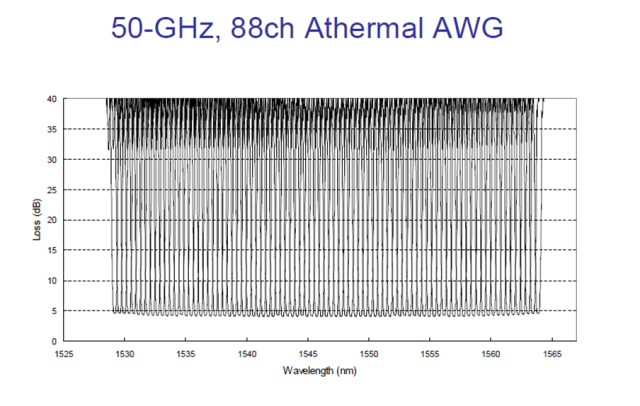
DWDM (Dense Wavelength Division Multiplexing) is a technology allowing high throughput capacity over longer distances commonly ranging between 44-88 channels/wavelengths and transferring data rates from 100Mbps up to 100Gbps per wavelength. Each wavelength can transparently carry wide range of services such as FE/1/10/40/100GBE, OTU2/OTU3/OTU4, 1/2/4/8/10/16GB FC,STM1/4/16/64, OC3/OC12/OC48/OC-192, HD/SD-SDI and CPRI.  The channel spacing of the DWDM solution is defined by the ITU.xxx (ask Omri) standard and can range from 25Ghz, 50GHz and 100GHz which is the most widely used today. Figure – 1 shows a DWDM spectral view of 88ch with 50GHz spacing.
50GHz spacing 88 DWDM channels/wavelengths
Figure -1: Spectral view of 50GHz spacing 88 DWDM channels/wavelengths
DWDM systems can provide up to 96 wavelengths (at 50GHz) of mixed service types, and can transport to distances up to 3000km by deploying amplifiers, as demonstrated in figure 2) and dispersion compensators thus increasing the fiber capacity by a factor of x100.  Due to its more precise and stabilized lasers, the DWDM technology tends to be more expensive at the sub-10G rates, but is a more appropriate solution and is dominating for 10G service rates and above providing large capacity data transport and connectivity over long distances at affordable costs. The DWDM solution today is often embedded with ROADM (Reconfigurable Optical Add Drop Multiplexer) which enables the building of flexible remotely managed infrastructure in which any wavelength can be added or dropped at any site. An example of DWDM equipment is well demonstrated by PL-1000, PL-1000GM, PL-1000GT, PL-1000RO, PL-2000 and PL-1000TN by DK Photonics Networks.
DWDM solution
Figure-2 Optical amplifier used in DWDM solution to overcome fiber attenuation and increase distance
CWDM (Coarse Wavelength Division Multiplexing) proves to be the initial entry point for many organizations due to its lower cost.  Each CWDM wavelength typically supports up to 2.5Gbps and can be expanded to 10Gbps support.  This transfer rate is sufficient to support GbE, Fast Ethernet or 1/2/4/8/10G FC, STM-1/STM-4/STM-16 / OC3/OC12/OC48, as well as other protocols.  The CWDM is limited to 16 wavelengths and is typically deployed at networks up to 80Km since optical amplifiers cannot be used due to the large spacing between channels. An example of this equipment is well demonstrated by PL-400, PL-1000E and PL-2000 by DK Photonics Networks.
It is important to note that the entire suite of DK Photonics’ equipment is designed to support both DWDM and CWDM technology by using standards based pluggable optical modules such as SFP, XFP and SFP+. The technology used is carefully calculated per project and according to customer requirements of distance, capacity, attenuation and future needs. DK Photonics also provides migration path from CWDM to DWDM enabling low entry cost and future expansion that can be viewed in the DWDM over CWDM technology page

WDM Installation
For designing and implementing a WDM network, there is a need to know some basic information regarding the infrastructure such as fiber type, attenuation of fiber, distance of fiber, network topology, service type, rate and connectivity. Based on this information, calculation of the optical link budget, OSNR (Optical Signal Noise Ratio) and dispersion can be performed in order to provide reliable, error free layer-1 optical solution.
DK Photonics’ WDM diversified equipment portfolio can provide either CWDM or DWDM solution for 4 wavelengths or 88 wavelengths ranging from few km to thousands of km and fit to the exact customer network needs. The network can be a point-to-point, linear add/Drop or ring Topology with passive Mux/DeMux or ROADM based infrastructure.
The WDM equipment serves as a demarcation point and is installed behind the Ethernet switch, router fiber channel SAN Fabric or SDH/SONET ADM coloring the fiber into different spectral wavelengths and multiplexing the rates fully isolated from each other over the same fiber to the remote site.  This allows transmission of multiple channels of different services and rates of data over the same fiber utilizing the fiber resources agnostically to the service type and rate.
The WDM technology can be applied to multiple applications such as connecting building service agnostic optical layer backbone,  data centers connectivity, Video broadcast, LTE fiber, cloud computing backbone, increasing existing fiber bandwidth and spectral efficiency.
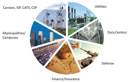
Figure 3 shows the main traditional and emerging CWDM and DWDM technology applications which keep  growing along with the rise of the cloud computing and CSP (Content Service Providers) as well as Smart phones and video applications causing constant increase  to the WDM technology deployment and new capacities such as 100G.
Main CWDM and DWDM technology applications
Figure 3 – Main CWDM and DWDM technology applications
DK Photonics’ WDM products designed for easy and fast implementation take up minimal space and use least power, thus providing the highest integration level of CWDM and DWDM networks in the smallest 1U footprint, while providing high ROI. Additionally, the CWDM DWDM optical network is managed remotely with either DK Photonics’ Light Watch NMS/EMS or the imbedded web based management system as well as via any 3rd party SNMP tool.
Read more related articles :
Filter-based WDM          CWDM            Mini CWDM Module       DWDM

Friday, September 6, 2013

40/100GbE MPO FIBER OPTIC CONNECTOR – NORTH AMERICA MARKET FORECAST


According to ElectroniCast, 12-fiber single mode MPO connector consumption value will increase 141% per year through 2016…
ElectroniCast Consultants, a leading market research & technology forecast consultancy addressing the fiber optics communications industry, today announced the release of their annual market forecast of the North American consumption of MPO Fiber Optic Connectors used in 40 and 100GbE communication links.
In 2006, the IEEE 802.3 working group formed the Higher Speed Study Group (HSSG) and found that the growth in bandwidth for network aggregation applications was outpacing the capabilities of networks employing link aggregation with 10 Gigabit Ethernet. (The standard was announced in July 2007 and was ratified on June 17, 2010).
Applications such as video, virtualization (cloud computing), switching/routing and convergence are driving the need for bandwidth expansion. We continue on the path of gradually developing of growth (and change) from 1G to 10G to 40G and 100G. For data center (DC) environments operating at 40GbE or 100GbE, fiber optic cabling is generally recommended because its reach supports a wider range of deployment configurations compared to copper solutions.
The capability to choose increased speed will enable networks to play with the 10GbE resources to the access layer allowing 40/100GbE to handle traffic at the aggregation and core layers. In this market research report, ElectroniCast Consultants provides their 2011-2016 forecast and analysis of MPO fiber optic connectors used in North American 40/100GbE optical communication networks.
The 10GbE movement into the data centers will continue; however, “future-proofing” is continuing with an accent (40/100G), which is driven by significant broadband expansion demands, especially in regards to network productivity and operating expenses (OPEX costs).
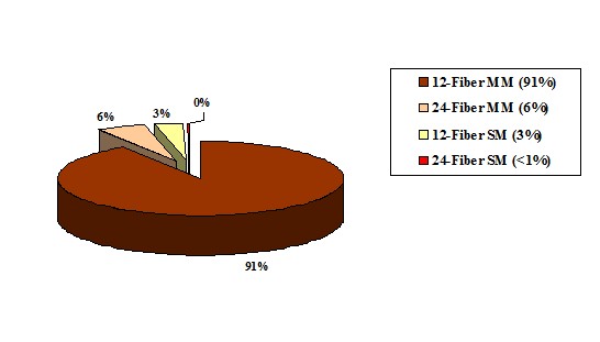
According to ElectroniCast, 12-fiber multimode MPO patchcord dominate the North American (Mexico, Canada and the United States) 40/100GbE MPO connector marketplace in 2012; however, 12-fiber single mode MPO connector consumption value will increase at the fastest pace of 141% per year through 2016.
According to ElectroniCast, 12-fiber multimode MPO connectors currently dominate the North American 40/100GbE MPO connector marketplace, based on consumption value…
40 and 100 GbE MPO Connector Value

North America Market Share (%) in 2012, by Type

mpo patchcord
(Source: ElectroniCast Consultants)
DK Photonicswww.dkphotonics.com specializes in designing and manufacturing of high quality optical passive components mainly for telecommunication, fiber sensor and fiber laser applications,such as PLC Splitter, WDM, FWDM, CWDM, DWDM, OADM, Circulator, Isolator, PM Circulator, PM Isolator, Fused Coupler, Fused WDM, Collimator, Optical Switch and Polarization Maintaining Components, Pump Combiner, High power isolator, Patch Cord and all kinds of connectors.

Tuesday, August 20, 2013

The Ion exchange process and the Glass choice of the PLC Splitter Chip

Along with development of the optical communication, its good environmental stability and compatibility with fiber, began to widely used optical communication components manufacturing.( Such as self-focusing lens, optical divider, optical amplifier, etc), And extend to the sensing area, (such as: all kinds of biological and chemical sensors , current sensors which is based on fading light waves, etc.)plc splitter
Glass ion-exchange technology has several one hundred years long history, Its earliest used to change the light absorption characteristics of glass, glass coloring,then, the technology is widely used in processing on the surface of the glass surface (such as touch screen add hard processing). Along with development of the optical communication, its good environmental stability and compatibility with fiber, began to widely used optical communication components manufacturing.( Such as self-focusing lens, optical divider, optical amplifier, etc), And extend to the sensing area, (such as: all kinds of biological and chemical sensors , current sensors which is based on fading light waves, etc.)
Current mainstream technology of PLC Splitter chip includes: PECVD technology, flame hydrolysis technology, glass ion exchange technology. Glass principle and technological process of ion exchange technology as shown in figure 1,figure 2. The main process flow flame hydrolysis technology shown in figure 3. The process characteristics of contrast see table 1. From years of use and reliability experiment, the two technologies are used in mass production and the performance is good.The features of PECVD/flame hydrolysis technique are that equipment and raw materials is the existing material, but its process is very complicated, the production cycle is long, the processing tolerance is small; Glass ion exchange technology is characterized by equipment and raw materials need special customized, but its technology is relatively simple, high production efficiency, process tolerance is larger, the chip cost is relatively low.
DK Photonicswww.dkphotonics.com specializes in designing and manufacturing of high quality optical passive components mainly for telecommunication, fiber sensor and fiber laser applications,such as PLC Splitter, WDM, FWDM, CWDM, DWDM, OADM,Optical Circulator, Isolator, PM Circulator, PM Isolator, Fused Coupler, Fused WDM, Collimator, Optical Switch and Polarization Maintaining Components, Pump Combiner, High power isolator, Patch Cord and all kinds of connectors.

Sunday, August 18, 2013

Telecommunication applications dominate the worldwide PLC splitter marketplace

Telecommunication applications dominate the worldwide PLC splitter marketplace…
ElectroniCast Consultants, a leading market/technology consultancy, today announced the report release of their market forecast of the global consumption of Planar Lightwave Circuit (PLC) splitters used in Fiber Optic Communication Networks.
This ElectroniCast study report details of last year’s consumption and forecasts to the year 2017 of PLC splitters by product-level (level of fabrication), in selected optical communication applications. There are actually three (3) separate market forecasts:
According to ElectroniCast, the PON, FTTx, and Telecommunication network applications dominate the worldwide PLC splitter compact device consumption value in 2012 with 77% in relative market share; followed by the cable TV segment, the PLC splitters used in Test/Measurement applications and then Harsh Environment (Military/Aerospace, Industrial) and finally Private Enterprise Networks.
In the report, ElectroniCast provides their market data covering the following optical communication applications:
  • Passive Optical Network (PON) / FTTX / Telecommunication Networks
  • Cable TV (CATV)
  • Fiber Optic Test/Measurement
  • Private Enterprise/Data Centers/Local Area Networks (LANs)
  • Harsh Environment (Military, Industrial, Other)
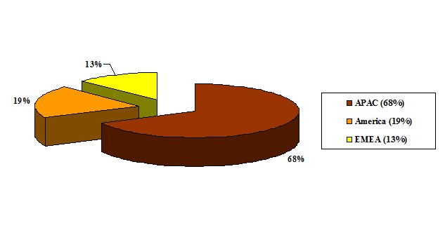
In 2012, the Asia Pacific region (APAC) region leads in the consumption of PLC splitter compact devices with 68% of the worldwide value, followed by the American region and finally the EMEA region.
According to ElectroniCast, the Asia Pacific region dominates the worldwide value of PLC splitters with 68% in 2012…
PLC Splitter Component-Level Compact Devices
2012 - Global Consumption Value Market Share (%), by Region
(Source: ElectroniCast Consultants)
PLC
DK Photonicswww.dkphotonics.com specializes in designing and manufacturing of high quality optical passive components mainly for telecommunication, fiber sensor and fiber laser applications,such as PLC Splitter, WDM, FWDM, CWDM, DWDM, OADM,Optical Circulator, Isolator, PM Circulator, PM Isolator, Fused Coupler, Fused WDM, Collimator, Optical Switch and Polarization Maintaining Components, Pump Combiner, High power isolator, Patch Cord and all kinds of connectors.

Wednesday, May 15, 2013

Basics of fiber optic networks

Hello again dear friends! Before that, we mostly discussed with you issues related to communications systems to transmit signals using electrical impulses, and now it is time to talk about another type of communication systems based on the use of optical pulses - fiber optic communication systems.

Existing communication systems that move data over copper, nice to everyone, except the distance to which they can transmit information (without intermediate amplification of points) is pretty limited. This eliminates the drawback  of fiber-optic transmission systems.

As probably not hard to guess all the usual copper communication cables are not suitable for optical signal transmission. Therefore, the fiber-optic networks used by another type of cable - optical cables. Outside (outer shell), these cables are similar to conventional copper cables (although there are some differences), but inside they contain are not familiar copper wires and optical fibers specially designed for the transmission of optical pulses. Typically, optical fibers made of quartz glass or certain types of plastic and have the following structure:
Design of optical fiber
As seen from the figure, the optical fiber is composed of two parts: the core and the shell. The core and the shell made of the characteristics of different materials, with consideration to the refractive index of the core was slightly higher than the refractive index of the shell. With such a ratio of the refractive indices, the light beam entering the core of the optical fiber, will be distributed by him due to the effect of total internal reflection occurs at the boundary between two media (the core and the cladding of an optical fiber).

By themselves, the optical fibers are relatively fragile, so they are covered by a special membrane buffer, and then combined in the optical modules, which are covered from above with additional protective layers. In general, the design of optical cable can be as follows (but in fact it may be different):
The design of an optical cable
For the introduction of an optical signal into an optical cable (and thus taking it to the other side of the cable) are special optical transceivers, which in practice is usually built into SFP modules are designed for installation in a variety of network devices, or directly in the optical device ports.
Skin and SFP modules
Consider how the direct connection of multiple network devices using fiber optics. Suppose we have two switches with connectors for SFP modules (if there is no switch with a socket for the SFP modules, you can use the circuit switch - media converter).
Switch with SFP connectors to install modules
In the SFP ports on the switch are installed SFP modules. Specific model SFP modules selected based on design requirements (required transmission distance, the type of optical cable, etc.).
Installing SFP Modules
For connectors installed SFP modules are connected optical patch cords (actually too optic cable, but containing only 1 or 2 fibers, and having a simple structure), the other end of the optical patch cords are connected to the terminals of optical distribution frame. Optical patch cords may have different optical connectors at its ends, the choice of a particular model (with certain connectors) is determined by optical connectors SFP modules and connectors optical distribution frame.
The appearance of the optical patch cord
Optical Distribution Frame roughly represents a metal box with connectors, which are connected outside optic patch cords and pigtails in (generally half the optical patch cord, used for okontsovyvaniya trunk optical cable). Also located inside the optical cross special cassettes and apparatus for fixing cables.
The appearance of the optical coupler
On the other side of the optical cross comes backbone fiber optic cable that will connect two remote sites.
The principle of operation of optical distribution frame
If you collect the whole scheme together, it will look like the following:
Connecting two remote sites using fiber-optic network
That's pretty hard not possible to connect two remote sites using the means of fiber-optic communications.

Monday, May 13, 2013

DK Photonics got a successful exhibition on OFC2013


Shenzhen, China, Apr. 10, 2013 -- DK Photonics Technology Co., Limited, one of the leading companies in designing and manufacturing of high quality optical passive components mainly for telecommunication, fiber sensor and fiber laser applications, announced that the Company got a successful show on OFC2013 in Anaheim. DK Photonics took two weeks to attend OFC2013 in Anaheim and visit customers in USA, and then came back last Monday with successful achievement.
On the exhibition, DK Photonics showed our traditional products such as PLC Splitter, WDM, FWDM, CWDM, DWDM, OADM, Optical Circulator, Optical Isolator, PM Circulator, PM Isolator, Fused Coupler, Fused WDM, Polarization Maintaining Components, Pump Combiner, High power Isolator, Patch Cord. At the same time, we took some innovative products such as 2000nm passive components to the show.
Through the OFC2013, customers got a deeper understanding to DK Photonics, such as products portfolio, inner management system, quality system and some research plan. Here we hope to express our salute to customers and DK Photonics would continue to give customers’ good service and quality products.
About DK Photonics
DK Photonics Technology Co., Limited is one of the leading companies in designing and manufacturing of high quality optical passive components mainly for telecommunication, fiber sensor and fiber laser applications. Headquartered and factory are located in Shenzhen of China.
DK Photonics have a group who has more than eight years working experience experts in the field of optical components and optical fiber laser; they formed a professional high-end R&D team. Our products are widely used in modern fiber lasers, amplifier, telecommunications, scientific research and other high-tech field of optical communication.
For more information about DK Photonics, please visit: http://www.dkphotonics.com/ , or email: info@dkphotonics.com