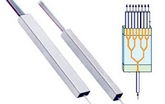
Showing posts with label plc splitter. Show all posts

Monday, January 5, 2015

How To Test Fiber Optic Splitters Or Other Passive Devices

fiber optic splitter is a device that splits the fiber optic light into several parts by a certain ratio. For example, when a beam of fiber optic light transmitted from a 1X4 equal ratio splitter, it will be divided into 4-fiber optic light by equal ratio that is each beam is 1/4 or 25% of the original source one. A Optical Splitter is different from WDM. WDM can divide the different wavelength fiber optic light into different channels. fiber optic splitter divide the light power and send it to different channels.
Most Splitters available in 900µm loose tube and 250µm bare fiber. 1×2 and 2×2 couplers come standard with a protective metal sleeve to cover the split. Higher output counts are built with a box to protect the splitting components.
Testing a coupler or splitter (both names are used for the same device) or other passive fiber optic devices like switches is little different from testing a patchcord or cable plant using the two industry standard tests, OFSTP-14 for double-ended loss (connectors on both ends) or FOTP-171 for single-ended testing.
First we should define what these passive devices are. An optical coupler is a passive device that can split or combine signals in optical fibers. They are named by the number of inputs and outputs, so a splitter with one input and 2 outputs is a 1×2 fiber splitter, and a PON splitter with one input and 32 outputs is 1×32 splitter. Some PON splitters have two inputs so it would be a 2X32. Here is a table of typical losses for splitters.
Splitter-Ratio
Important Note! Mode Conditioning can be very important to testing couplers. Some of the ways they are manufactured make them very sensitive to mode conditioning, especially multimode but even singlemode couplers. Singlemode couplers should always be tested with a small loop in the launch cable (tied down so it does not change and set the 0dB reference with the loop.) Multimode couplers should be mode conditioned by a mandrel wrap or similar to ensure consistency.
Let’s start with the simplest type. Shown below is a simple 1X2 splitter with one input and two outputs. Basically, in one direction it splits the signal into 2 parts to couple to two fibers. If the split is equal, each fiber will carry a signal that is 3dB less than the input (3dB being a factor of two) plus some excess loss in the coupler and perhaps the connectors on the splitter module. Going the other direction, signals in either fiber will be combined into the one fiber on the other side. The loss is this direction is a function of how the coupler is made. Some couplers are made by twisting two fibers together and fusing them in high heat, so the coupler is really a 2X2 coupler in which case the loss is the same (3dB plus excess loss) in either direction. Some splitters use optical integrated components, so they can be true splitters and the loss in each direction may different.
optical coupler
So for this simple 1X2 splitter, how do we test it? Simply follow the same directions for a double-ended loss test. Attach a launch reference cable to the test source of the proper wavelength (some splitters are wavelength dependent), calibrate the output of the launch cable with the meter to set the 0dB reference, attach to the source launch to the splitter, attach a receive launch cable to the output and the meter and measure loss. What you are measuring is the loss of the splitter due to the split ratio, excess loss from the manufacturing process used to make the splitter and the input and output connectors. So the loss you measure is the loss you can expect when you plug the splitter into a cable plant.
To test the loss to the second port, simply move the receive cable to the other port and read the loss from the meter. This same method works with typical PON splitters that are 1 input and 32 outputs. Set the source up on the input and use the meter and reference cable to test each output port in turn.
What about the other direction from all the output ports? (In PON terms, we call that upstream and the other way from the 1 to 32 ports direction downstream.) Simply reverse the direction of the test. If you are tesing a 1X2 splitter, there is just one other port to test, but with a 1X32, you have to move the source 32 times and record the results on the meter.
fiber-splitter
What about multiple input and outputs, for example a 2X2 coupler? You would need to test from one input port to the two outputs, then from the other input port to each of the two outputs. This involves a lot of data sometimes but it needs to be tested.
There are other tests that can be performed, including wavelength variations (test at several wavelengths), variations among outputs (compare outputs) and even crosstalk (put a signal on one output and look for signal on other outputs.)
Once installed, the splitter simply becomes one source of loss in the cable plant and is tested as part of that cable plant loss for insertion loss testing. Testing splitters with an OTDR is not the same in each direction.
There are other passive devices that require testing, but the test methods are similar.
Fiber optic switches are devices that can switch an input to one of several outputs under electronic control. Test as you would the splitter as shown above. Switches may be designed for use in only one direction, so check the device specifications to ensure you test in the proper direction. Switches may also need testing for consistency after multiple switch cycles and crosstalk.
Attenuators are used to reduce signal levels at the receiver to prevent overloading the receiver. There is a page on using attenuators that you should read. If you need to test an attenuator alone, not part of a system, use the test for splitters above by using the attenuator to connect the launch and receive cables to see if the loss is as expected.
Wavelength-division multiplexers can be tricky to test because they require sources at a precise wavelenth and spectral width, but otherwise the test procedures are similar to other passive components.
Fiber optic couplers or splitters are available in a wide range of styles and sizes to split or combine light with minimal loss. All couplers are manufactured using a very simple proprietary process that produces reliable, low-cost devices. They are physically rugged and insensitive to operating temperatures. Couplers can be fabricated in custom fiber lengths and/or with terminations of any type.
DK Photonics – www.dkphotonics.com  specializes in designing and manufacturing of high quality optical passive components mainly for telecommunication, fiber sensor and fiber laser applications,such as PLC Splitter, WDM, FWDM, CWDM, DWDM, OADM,Optical Circulator, Isolator, PM Circulator, PM Isolator, Fused Coupler, Fused WDM, Collimator and Polarization Maintaining Components, Pump Combiner, High power isolator, Patch Cord and all kinds of connectors.

Monday, October 20, 2014

Introduction of FBG Filter Embedded Adaptor-FBG filters for live network monitoring using in FTTH

Introduction of FBG Filter Embedded Adaptor-FBG filters for live network monitoring using in FTTH
FBG Filter Embedded Adaptor
FBG Filter Embedded Connector
FBG filters for FTTx applications are reflective filters integrated in the LC or SC adapters, which reflect the 1625 nm wavelength and transmit all other (i.e. 1310, 1490 and 1550 nm). They can be used to monitor live network utilizing OTDR operating at 1625 or 1650 nm. End-to-end OTDR measurements from OLT to ONT are typically difficult due to the high point insertion loss introduced by the splitter and due to the required very good spatial resolution. The use of the 1625 nm reflectors is an efficient and cost-effective way of reducing the required dynamic range of the OTDR. The 1625 reflectors  are currently considered the best way of implementing  real time end-to-end (OLT to ONT) monitoring of the optical layer in live FTTx networks.
FBG filter
More information for the FBG Filter Embedded Connector
DK Photonics – www.dkphotonics.com  specializes in designing and manufacturing of high quality optical passive components mainly for telecommunication, fiber sensor and fiber laser applications,such as PLC Splitter, WDM, FWDM, CWDM, DWDM, OADM,Optical Circulator, Isolator, PM Circulator, PM Isolator, Fused Coupler, Fused WDM, Collimator, Optical Switch and Polarization Maintaining Components, Pump Combiner, High power isolator, Patch Cord and all kinds of connectors.

Monday, October 13, 2014

DK Photonics:Huawei to invest over $4 billion in fixed broadband technology in 3 years

Telecom network vendor Huawei on Thursday said it will be investing over $4 billion in fixed broadband (FBB) technology research and development over the next three years.
Huawei’s plans to invest significantly in fixed broadband technology reflects a report from Dell’Oro Group that said wireline telecom markets will grow at a CAGR of 3 percent against 1 percent growth for wireless between 2013 and 2018.
In August, Dell’Oro Group said the combined service provider equipment markets will grow at a CAGR of 2 percent between 2013 and 2018 — after recording a CAGR of -1 percent between 2008 and 2013.
Huawei said the $4 billion investment will focus on products and solutions which will support their customers with providing an improved service experience for end users.
Huawei Products and Solutions President Ryan Ding said: “Our investment will further develop technological advances, help customers increase their competitiveness and decrease overall operating costs.”
Existing technologies are changing, next-generation High-Efficiency Video Coding is maturing, 4k panel and content production costs are reducing and the development of the 4k video industry, are all driving new solutions.
Huawei to invest over $4 billion in fixed broadband technology in 3 years
As LTE and 5G deployment continues, construction of high-performance networks which guarantee better customer experience will be expected by telecom operators. Huawei said FBB technologies will be progressed by leveraging big data, data centers and cloud computing to meet their needs.
Tam Dell’Oro, president and founder of Dell’Oro Group, said: “While we believe carriers will continue to enhance their wireless networks, we anticipate carriers will put more emphasis on backhauling traffic which means improving their fixed line networks in the next five years.”
Huawei today said it will innovate Software Defined Networking (SDN), Network Functions Virtualization (NFV) to initiate open broadband networks that help customers simplify operations and management, realize service innovation and improve network efficiency.
For next-generation networks, Huawei will conduct research and develop on new key technologies and architectures for IP and all-optical networks, advancing FBB network development.
Fixed LTE broadband access gains
At present, 1.26 billion households do not have DSL, cable, or fiber-optic broadband. Fixed and mobile telecoms are looking to LTE to make the connection.
“By the end of 2014, there will be 14.5 million residential and commercial premises with fixed LTE broadband access. By 2019, that figure should grow to 123 million,” said Jake Saunders, VP and 4G practice director at ABI Research.
ITU pitches for broadband
ITU, a telecom industry association under the aegis of UN, says more than 40 percent of the world’s people are already online, with the number of Internet users rising from 2.3 billion in 2013 to 2.9 billion by the end of this year.
Over 2.3 billion people will access mobile broadband by end 2014, climbing steeply to a predicted 7.6 billion within the next five years.
ITU says there are now over three times as many mobile broadband connections as there are conventional fixed broadband subscriptions.
Huawei on green telecom
Meanwhile, Eric Xu, Rotating chief executive officer, Huawei, said: “Huawei is committed to socio-economic and environmental sustainability. We leverage our expertise to bridge the digital divide and deliver high-quality digital connectivity for all.”
“We always honor our commitment to supporting secure and stable network operations anytime, anywhere. We contribute to low-carbon economies by helping customers and industries improve productivity and reduce energy consumption,” said Xu at the sixth Global Supplier Sustainability Conference in Shenzhen, China.
DK Photonics – www.dkphotonics.com  specializes in designing and manufacturing of high quality optical passive components mainly for telecommunication, fiber sensor and fiber laser applications,such as PLC Splitter, WDM, FWDM, CWDM, DWDM, OADM,Optical Circulator, Isolator, PM Circulator, PM Isolator, Fused Coupler, Fused WDM, Collimator, Optical Switch and Polarization Maintaining Components, Pump Combiner, High power isolator, Patch Cord and all kinds of connectors.

Wednesday, September 17, 2014

Differences Between FBT Coupler and PLC splitters

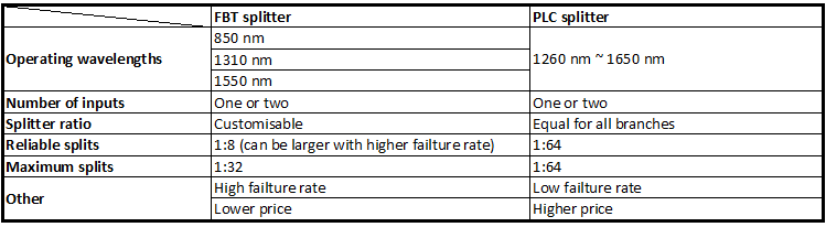
Optical networks require signal being splitted somewhere in design to serve for multiple customers. Splitter technology has made a huge step forward in the past few years by introducing PLC (Planar Lightwave Circuit) splitter. It has proven itself as a higher reliable type of device compared to the traditional FBT (Fused Biconical Taper) splitter. While being similar in size and outer appearance, both types of splitters provide data and video access for business and private customers. However, internally the technologies behind these types vary, thus giving  service providers a possibility to choose a more appropriate solution.
FBT splitter is made out of materials that are easily available, for example steel, fiber, hot dorm and others. All of these materials are low-price, which determines the low cost of the device itself. The technology of the device manufacturing is relatively simple, which has the impact on its price as well. In scenario where multiple splits are needed, the size of the device may become an issue. It is important to keep in mind that splitters are being deployed in the fields either in cabinets or in strand mountings, so the size of device plays a critical role. FBT splitters only support three wavelengths (850/1310/1550 nm) which makes these devices unable to operate on other wavelengths. Inability of adjusting wavelengths makes FBT splitters less customizable for different purposes. Moreover, the devices are to a high extent temperature sensitive, providing a stable working range of -5 to 75 C. In certain areas, such as Scandinavian countries this temperature restrictions may be crucial. The signal processed by FBT splitters cannot be splitted evenly due to lack of management of the signals
PLC splitter manufacturing technology is more complex. It uses semiconductor technology (lithography, etching, developer technology) production, hence it is more difficult to manufacture. Therefore, the price of the device is higher. However, there is a number of advantages the device possesses. The size of the device is compact, compared to FBT splitters, making it suitable for density applications. PLC splitter operates at wider temperature range (-40 to 85 C), allowing its deploying in the areas of extreme climate. The split ratio goes up to 64, providing a high reliability. Furthermore, the signal can be split equally due to technology implemented. A range of wavelengths (1260 – 1650 nm) is provided, so the wavelengths are adjustable. Critical points of the device that might fail are input and output, so the general risk of failure is low.
Differences Between FBT and PLC splitters
 Table 1. FBT and PLC splitter feature comparison
DK Photonics – www.dkphotonics.com  specializes in designing and manufacturing of high quality optical passive components mainly for telecommunication, fiber sensor and fiber laser applications,such as PLC Splitter, WDM, FWDM, CWDM, DWDM, OADM,Optical Circulator, Isolator, PM Circulator, PM Isolator, Fused Coupler, Fused WDM, Collimator, Optical Switch and Polarization Maintaining Components, Pump Combiner, High power isolator, Patch Cord and all kinds of connectors.

Tuesday, September 9, 2014

Ovum: Optical components market to grow 8% in 2014 from $6.8 bn in 2013

The global optical components (OC) market is expected to grow 8 percent in 2014 from $6.8 billion in 2013, said Ovum.
In 2013, the OC market increased 3 percent from 2012. Ovum said main growth drivers in 2013 were data communication sales driven by large data centers, 100G coherent demand, and unexpected growth in sales of transceivers for fiber-to-the-antenna applications for 4G build-outs.
“Demand for 100G metro–optimized transmission gear will begin shipments and ramp in 2015. Multiple component vendors introduced components and pluggable optics for 100GHz DWDM in anticipation. Opportunities are also emerging in the data center for high-speed interconnects,” said Daryl Inniss, practice leader for Telecoms Components at Ovum.
In the first quarter of 2014, the optical components market declined 1 percent sequentially and grew 7 percent compared to the year-ago period.  New lower telecom prices were one of the main reasons for the marginal growth in OC on quarter-on-quarter basis.
Ovm said demand for 100G components for coherent transmission in WAN, datacom transceivers at 10 and 40G, and fiber-to-the-antenna transceivers is expected to continue. Traffic continues to increase, and high-speed optics being used in new applications are helping to drive the market forward.
Global-optical-components-market-forecast
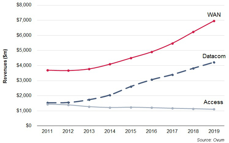
The WAN OC segment, which includes components in telecom carriers’ core and metro networks, the largest segment, will grow at a compound annual growth rate (CAGR) of 11 percent to $7 billion in 2019. Demand for 100G components and modules is a big driver for growth in WAN.  Ovum expects strong demand for pluggable coherent transceivers in 2015.
Datacom will be expanding at a 16 percent CAGR to reach $4.2 billion in 2019 — led by demand for 10 and 40G components in the early years and then 100G in the later years driven by the availability of server ports supporting data rates greater than 10G.
Access — including CATV, FTTx and transceivers for the fiber-to-the-antenna application — will decline at 2 percent CAGR to $1.1 billion in 2019. The decline will be driven by the FTTx application, where volumes are nearly constant through the forecast period but price declines are projected to pull down revenues.

DK Photonics – www.dkphotonics.com  specializes in designing and manufacturing of high quality optical passive components mainly for telecommunication, fiber sensor and fiber laser applications,such as PLC Splitter, WDM, FWDM, CWDM, DWDM, OADM,Optical Circulator, Isolator, PM Circulator, PM Isolator, Fused Coupler, Fused WDM, Collimator, Optical Switch and Polarization Maintaining Components, Pump Combiner, High power isolator, Patch Cord and all kinds of connectors.

Wednesday, August 20, 2014

Huawei, Rostelecom collaborate on FTTH distribution boxes—DK Photonics

Huawei says it has collaborated with Russian service provider Rostelecom to develop floor distribution boxes (FDBs) for use in Rostelecom’s flexible fiber to the home (FTTH) deployments. The FDBs will help improve the efficiency of the operator’s FTTH deployments, particularly in sparsely populated areas, Huawei says.
Rostelecom is under a mandate from the Russian government to connect 13 million CWDM Module users by 2015, Huawei says. This task is complicated by the fact that much of the operator’s footprint covers rural areas.
To improve deployment efficiency, Huawei says it recommended what it calls "the thin-covered network deployment model." According to the model, fiber-optic networks are constructed to user access points and the FDBs, the latter of which are used as the interface between the outside plant and the inside plant. As the network expands and more users are connected, pre-made drop cables can be used for plug-and-play, quick service provisioning.
The customized FDBs were designed for success-based deployment. Rostelecom can deploy FDBs that provide access to a single user, then add connections as many as four or eight users as take rates improve. Technicians can complete the expansion in one minute without the use of tools, Huawei says.
Huawei and Rostelecom will further collaborate on other network elements, including the closure, optical splitter, and fiber distribution terminal (FDT), the technology provider added.
For more information on FTTx products, visit the DK Photonics Website.
DK Photonics – www.dkphotonics.com  specializes in designing and manufacturing of high quality optical passive components mainly for telecommunication, fiber sensor and fiber laser applications,such as PLC Splitter, WDM, FWDM, CWDM, DWDM, OADM,Optical Circulator, Isolator, PM Circulator, PM Isolator, Fused Coupler, Fused WDM, Collimator, Optical Switch and Polarization Maintaining Components, Pump Combiner, High power isolator, Patch Cord and all kinds of connectors.

Saturday, April 12, 2014

Planar Lightwave Circuit Splitters Market Forecast

Fiber-to-the-Home deployment dominates the PLC splitter marketplace…

Fiber-to-the-Home deployment dominates the PLC splitter marketplace…
Aptos, CA (USA) – February 20, 2014  -- ElectroniCast Consultants, a leading market/technology consultancy, today announced the report release of their market forecast of the global consumption of Planar Lightwave Circuit (PLC) splitters used in Fiber Optic Communication Networks.
According to the ElectroniCast market study, the consumption value of component-level (compact device) PLC splitters reached $529.6 million in 2013. PLC splitters will continue to contribute an important role in Fiber to the Home (FTTH) networks by allowing a single passive optical network (PON) interface to be shared among many subscribers.  PLC splitters are available in compact sizes; therefore, they can be used in aerial apparatus, pedestals or in-ground as well as rack mount or other module-based value-added product. Installation is simple using a variety of connector types or fusion splicing.
“The PON-based Fiber-to-the-Home network application dominates the worldwide PLC splitter consumption value in 2014,” stated Stephen Montgomery, Director of the Fiber Optics Components group at ElectroniCast Consultants.
“The American region is forecast for flat annual growth (just over 1%); however, the EMEA region is set for 7% per year and the APAC region is forecast to increase at 15% per year, for the component-level PLC splitters, during the 2013-2018 timeframe cover by the ElectroniCast study,” Montgomery added.
DK Photonics – www.dkphotonics.com  specializes in designing and manufacturing of high quality optical passive components mainly for telecommunication, fiber sensor and fiber laser applications,such as PLC Splitter, WDM, FWDM, CWDM, DWDM, OADM,Optical Circulator, Isolator, PM Circulator, PM Isolator, Fused Coupler, Fused WDM, Collimator, Optical Switch and Polarization Maintaining Components, Pump Combiner, High power isolator, Patch Cord and all kinds of connectors.

Tuesday, December 10, 2013

Comparation Between EPON and GPON


With the continuous progress of science and technology, the Internet has gradually gone into the homes of the ordinary people, and the speed of broadband has increasingly become the topic of people in the entertainment and work often, from narrowband dial-up to broadband Internet, and then the fiber access Internet, broadband network, the rapid pace of PON technology gradually come to the front. Currently, there are two quite compelling PON standard has been officially released, which are GPON standard developed by the ITU / FSAN and EPON standard developed by IEEE 802.3ah working group. PON technology has been no doubt the ultimate solution for the future FTTH era. EPON and GPON who will the dominant FTTH tide has become a new hot debate. What's the difference between EPON and GPON?
GPON and EPON Differences
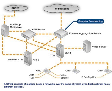
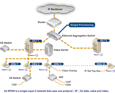
Perhaps the most dramatic distinction between the two protocols is a marked difference in architectural approach. GPON provides three Layer 2 networks: ATM for voice, Ethernet for data, and proprietary encapsulation for voice. EPON, on the other hand, employs a single Layer 2 network that uses IP to carry data, voice, and video.
A multiprotocol transport solution supports the GPON structure (Figure 1). Using ATM technology, virtual circuits are provisioned for different types of services sent from a central office location primarily to business end users. This type of transport provides high-quality service, but involves significant overhead because virtual circuits need to be provisioned for each type of service. Additionally, GPON equipment requires multiple protocol conversions, segmentation and reassembly (SAR), virtual channel (VC) termination and point-to-point protocol (PPP).
Figure 1: Diagram showing a typical GPON network.
EPON provides seamless connectivity for any type of IP-based or other "packetized" "communications" (Figure 2). Since Ethernet devices are ubiquitous from the home network all the way through to regional, national and worldwide backbone networks, implementation of EPONs can be highly cost-effective. Furthermore, based on continuing advances in the transfer rate of Ethernet-based transport — now up to 10 Gigabit Ethernet — EPON service levels for customers are scalable from T1 (1.5 Mbit/s) up through 1 Gbit/s.
Figure 2: Diagram showing a typical EPON network.
Upstream Bandwidth
Subtracting the various system run overhead from the total bandwidth of the system uplink transmission is the upstream available bandwidth. It has a great relationship with the number of the ONU contained in the system, DBA (Dynamic Bandwidth Allocation) algorithm polling cycle, the type of bearer services, as well as the various business proportion. EPON and GPON are broadband access technology, hosted business IP data services. Below we will calculate the uplink the beared pure IP services available bandwidth of EPON and GPON that contain 32 ONUs, fiber optic coupler,the case of polling period 750s.
EPON
EPON upstream rate is 1.25 Gbit/s. Because the 8B/10B line coding, each 10bit are 8bit valid data, so its effective upstream transmission bandwidth is 1 Gbit/s. EPON upstream overhead of running the system and its proportion of the total bandwidth are as following:
1. Used for the the burst reception of physical layer overhead: about 3.5%;
2. Ethernet frame encapsulation overhead: about 7.4%;
3. MPCP (Multi-Point Control Protocol) and OAM operation and management of maintenance protocol overhead: about 2.9%;
4. DBA algorithm resulting in the remaining time slots (that is not sufficient to transfer a complete Ethernet frame time slot) wasted: about 0.6%;
5. EPON upstream total overhead is all of the above about 144 Mbit/s, the available bandwidth is about 856 Mbit/s.
GPON
GPON supports a variety of rate levels, has asymmetric rate that downlink is 2.5Gbps or 1.25Gbps, the upgoing is 1.25Gbps or 622 Mbps. NRZ encoding the uplink total bandwidth for 1.244 Gbit/s, GPON upstream overhead of running the system as following:
1. The proportion of its total bandwidth is used for the the burst reception of physical layer overhead: about 2.0%;
2. GEM (GPON encapsulation method) frame and the Ethernet frame encapsulation overhead: about 5.8%;
3. The PLOAM (physical layer operation, management and maintenance) protocol overhead: about 2.1%;
4. Remaining slots of the DBA algorithm introduced the additional encapsulation overhead: about 0.8%.
5. GPON upstream total overhead is all of the above about 133 Mbit/s, the available bandwidth about 1111 Mbit/s.

Tuesday, August 20, 2013

The Ion exchange process and the Glass choice of the PLC Splitter Chip

Along with development of the optical communication, its good environmental stability and compatibility with fiber, began to widely used optical communication components manufacturing.( Such as self-focusing lens, optical divider, optical amplifier, etc), And extend to the sensing area, (such as: all kinds of biological and chemical sensors , current sensors which is based on fading light waves, etc.)plc splitter
Glass ion-exchange technology has several one hundred years long history, Its earliest used to change the light absorption characteristics of glass, glass coloring,then, the technology is widely used in processing on the surface of the glass surface (such as touch screen add hard processing). Along with development of the optical communication, its good environmental stability and compatibility with fiber, began to widely used optical communication components manufacturing.( Such as self-focusing lens, optical divider, optical amplifier, etc), And extend to the sensing area, (such as: all kinds of biological and chemical sensors , current sensors which is based on fading light waves, etc.)
Current mainstream technology of PLC Splitter chip includes: PECVD technology, flame hydrolysis technology, glass ion exchange technology. Glass principle and technological process of ion exchange technology as shown in figure 1,figure 2. The main process flow flame hydrolysis technology shown in figure 3. The process characteristics of contrast see table 1. From years of use and reliability experiment, the two technologies are used in mass production and the performance is good.The features of PECVD/flame hydrolysis technique are that equipment and raw materials is the existing material, but its process is very complicated, the production cycle is long, the processing tolerance is small; Glass ion exchange technology is characterized by equipment and raw materials need special customized, but its technology is relatively simple, high production efficiency, process tolerance is larger, the chip cost is relatively low.
DK Photonicswww.dkphotonics.com specializes in designing and manufacturing of high quality optical passive components mainly for telecommunication, fiber sensor and fiber laser applications,such as PLC Splitter, WDM, FWDM, CWDM, DWDM, OADM,Optical Circulator, Isolator, PM Circulator, PM Isolator, Fused Coupler, Fused WDM, Collimator, Optical Switch and Polarization Maintaining Components, Pump Combiner, High power isolator, Patch Cord and all kinds of connectors.

Sunday, August 18, 2013

Telecommunication applications dominate the worldwide PLC splitter marketplace

Telecommunication applications dominate the worldwide PLC splitter marketplace…
ElectroniCast Consultants, a leading market/technology consultancy, today announced the report release of their market forecast of the global consumption of Planar Lightwave Circuit (PLC) splitters used in Fiber Optic Communication Networks.
This ElectroniCast study report details of last year’s consumption and forecasts to the year 2017 of PLC splitters by product-level (level of fabrication), in selected optical communication applications. There are actually three (3) separate market forecasts:
According to ElectroniCast, the PON, FTTx, and Telecommunication network applications dominate the worldwide PLC splitter compact device consumption value in 2012 with 77% in relative market share; followed by the cable TV segment, the PLC splitters used in Test/Measurement applications and then Harsh Environment (Military/Aerospace, Industrial) and finally Private Enterprise Networks.
In the report, ElectroniCast provides their market data covering the following optical communication applications:
  • Passive Optical Network (PON) / FTTX / Telecommunication Networks
  • Cable TV (CATV)
  • Fiber Optic Test/Measurement
  • Private Enterprise/Data Centers/Local Area Networks (LANs)
  • Harsh Environment (Military, Industrial, Other)
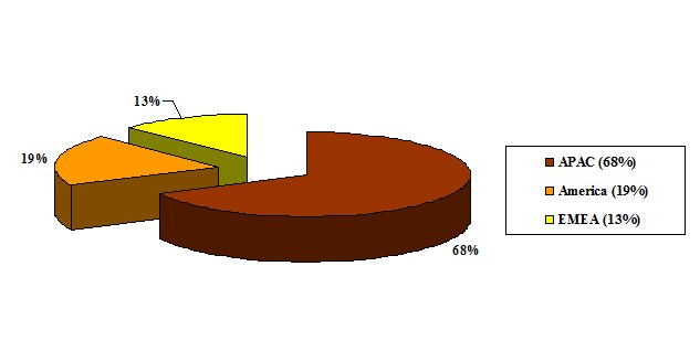
In 2012, the Asia Pacific region (APAC) region leads in the consumption of PLC splitter compact devices with 68% of the worldwide value, followed by the American region and finally the EMEA region.
According to ElectroniCast, the Asia Pacific region dominates the worldwide value of PLC splitters with 68% in 2012…
PLC Splitter Component-Level Compact Devices
2012 - Global Consumption Value Market Share (%), by Region
(Source: ElectroniCast Consultants)
PLC
DK Photonicswww.dkphotonics.com specializes in designing and manufacturing of high quality optical passive components mainly for telecommunication, fiber sensor and fiber laser applications,such as PLC Splitter, WDM, FWDM, CWDM, DWDM, OADM,Optical Circulator, Isolator, PM Circulator, PM Isolator, Fused Coupler, Fused WDM, Collimator, Optical Switch and Polarization Maintaining Components, Pump Combiner, High power isolator, Patch Cord and all kinds of connectors.

Monday, May 13, 2013

DK Photonics got a successful exhibition on OFC2013


Shenzhen, China, Apr. 10, 2013 -- DK Photonics Technology Co., Limited, one of the leading companies in designing and manufacturing of high quality optical passive components mainly for telecommunication, fiber sensor and fiber laser applications, announced that the Company got a successful show on OFC2013 in Anaheim. DK Photonics took two weeks to attend OFC2013 in Anaheim and visit customers in USA, and then came back last Monday with successful achievement.
On the exhibition, DK Photonics showed our traditional products such as PLC Splitter, WDM, FWDM, CWDM, DWDM, OADM, Optical Circulator, Optical Isolator, PM Circulator, PM Isolator, Fused Coupler, Fused WDM, Polarization Maintaining Components, Pump Combiner, High power Isolator, Patch Cord. At the same time, we took some innovative products such as 2000nm passive components to the show.
Through the OFC2013, customers got a deeper understanding to DK Photonics, such as products portfolio, inner management system, quality system and some research plan. Here we hope to express our salute to customers and DK Photonics would continue to give customers’ good service and quality products.
About DK Photonics
DK Photonics Technology Co., Limited is one of the leading companies in designing and manufacturing of high quality optical passive components mainly for telecommunication, fiber sensor and fiber laser applications. Headquartered and factory are located in Shenzhen of China.
DK Photonics have a group who has more than eight years working experience experts in the field of optical components and optical fiber laser; they formed a professional high-end R&D team. Our products are widely used in modern fiber lasers, amplifier, telecommunications, scientific research and other high-tech field of optical communication.
For more information about DK Photonics, please visit: http://www.dkphotonics.com/ , or email: info@dkphotonics.com

Friday, May 10, 2013

Application of fiber optic high power isolator and some mutual problems about its production process


1 introduction
Semiconductor lasers, optical amplifiers and optical fiber lasers from the connector, fusion point, filter the reflection light is very sensitive, and may cause performance deterioration and even damaged, requiring a optical isolator to prevent the reflection of light. The optical isolator is permitted only light along one direction through and in the opposite direction blocks light through the optical passive devices. In the optical fiber communication, optical fiber reflection light through the optical isolator can be a good isolation. In the fiber laser applications, optical isolators are usually used in the optical path to avoid the light path of the light source, the echo on the pumping source and other light emitting device causes interference and damage. Isolators’s isolation represents the optical isolator to echo the isolation (blocking) ability.
2 optical isolator principle
Optical isolator using magnetic optical crystal Faraday effect ( also known as the Faraday effect ). In 1845, Faraday first observed with optical material under the action of magnetic field to make the material in the direction of polarization rotation, therefore often called the Faraday effect. In Faraday effect, the rotation of the polarization direction direction and magnetic field, and the orientation of the light transmitting is independent of the forward and reverse, and we usually in the index of refraction, reflection phenomena seen in the reversibility of optical path difference. Along the magnetic field direction of transmission line polarized, the polarization direction rotating angle θand magnetic field strength of B and L is proportional to the product of the length of the material, the proportion coefficient is what we often say that the Wilde constant. Optical isolator based on polarization characteristics can be divided into polarization-independent and polarization dependent type. These two kinds of isolators are used with the Faraday effect in magneto-optic crystal, Faraday magnetic medium in 1~2μ m wavelength range usually adopts the optical loss low yttrium iron garnet ( YIG ) single crystals. Model of input and output of the fiber optical isolator has fairly good performance, the minimum insertion loss of approximately 0.5 dB, the isolation of up to 35 60 dB, a maximum of 70 dB.   The optical isolator using most still is polarization independent type, its principle is shown in Figure 1, using the forward and reverse transmission optical path is inconsistent, it is this time signal transmission is not reversible, thereby forming isolation. The typical structure of only four major components: the magnetic ring, a Faraday rotator, two pieces of LiNbO3 wedge angle piece, with a pair of fiber collimator, can be made into an in-line optical isolators.      
Positive transmission: the parallel light beam from the collimator, into the first wedge angle piece P1, beam is divided into o light and e light, the polarization direction perpendicular to the propagation direction, forming an included angle. When they pass through 45o Faraday rotator, emitted by the o light and e light polarizing surfaces of respective to the same direction of rotation 45o, because the second wedge-shaped plate P2 crystal axis relative to the first wedge angle piece is just in a 45o angle, so o light and e light is refracted into a small space, synthesis. Parallel light, and then by another collimator is coupled to the optical fiber core. In this case, the input optical power only a very small fraction of outage, this loss is called isolator insertion loss.
Reverse transmission: when a beam of parallel light reverse transmission, first with a P2 crystal, divided into the polarization direction and P1 crystal axis respectively in 45o angle o light and E light. Due to the Faraday effect non reciprocity, O Light and e light through the Faraday rotator, the polarization direction to the same direction of rotation 45 °, so the original o light and e light in the second wedge-shaped plate ( P1 ) later became e and O light. Because the refractive index differences, the two light beam in the P1 no longer possible synthesis of a parallel beam of light, but in different directions to the refraction of light, e and o are further separated from a larger perspective, even after a GRIN lens coupling, can not enter the fiber core to, from and achieved reverse isolation purposes. The transmission loss is bigger, this loss is called isolators isolation.
3 main technical parameters of optical isolator
The optical isolator, the main technical indicators have insertion loss, reverse isolation, return loss, polarization dependent loss, polarization mode dispersion.
(1) insertion loss ( Insertion Loss ): isolator core mainly comprises a Faraday rotator and a two piece of LN wedge angle piece, a Faraday rotator extinction ratio higher, lower reflectivity, absorption coefficient is smaller, insertion loss is smaller, general Faraday rotator loss is about 0.02 0.06dB. Parallel light pass through the isolator core, will be divided into o, e beams of parallel light. Due to the inherent characteristics of birefringent crystals, O Light and e light can not fully converge, which may cause additional insertion loss.
(2) reverse isolation ( Isolation ): reverse isolation isolator is one of the most important indicators, which characterizes the isolator on the reverse transmission attenuation ability. Effect of isolator isolation of many factors : 1 ) the isolation and polarizer from the Faraday rotator is related to the distance; 2) isolation and optical element surface reflectance relationship. Isolator optical element surface reflectance is bigger, the isolation degree is worse. The practical technology that R must be less than 0.25%, to ensure the isolation degree is greater than 40 dB; 3) isolation of polarimeter and wedge angle, spacing. Double refraction crystal yttrium vanadate ( YVO4 ) of the optical isolator, when the wedge angle of less than 2°, isolation with the perspective of the increase, when the wedge angle is greater than 2°, change is much smaller, approximately stable at about 43.8 dB. Optical isolation with the increase of the distance between the change range is not big, because isolation depends mainly on the reverse output light and the angle between the optical axis; 4) isolation and crystal axis angular relationship relative. The two polarizers and rotator crystal axis relative angle to the isolation effect is maximum, when the angle is greater than the difference between the 0.3o isolation will not be greater than 40 dB; 5) the two polarizer extinction ratio, crystal thickness on isolation effect; 6) the influence of temperature and magnet. In Faraday effect, Verdet constant is a function of temperature, so the Faraday rotation angle will change with the temperature, and the temperature will be on permanent magnet performance impact, so it is one of important factors.
(3) return loss ( Return Loss ): optical return loss refers to the positive incident to the isolator optical power and along the input path to return to the isolator input port of the optical power ratio, this is one of the important indicators, because the echo intensity, isolation would be affected by. Isolator echo loss by each element and the air refractive index mismatch caused by the reflection. The generally planar element caused by echo return loss is controlled in 14 dB, through antireflective film and surface polishing can make the return loss reached more than 60 dB. Optical return loss mainly from the collimated light path (i.e., collimator parts), through the theoretical calculation when the slant angle 8 °, return loss is greater than 65 dB.
(4) the polarization-dependent loss ( Polarization Dependent Loss, PDL ) :PDL and insertion loss is different, it is a when the input light polarization state changes and other parameters unchanged, the insertion loss of maximum variation, is a measure of device insertion loss by effect of polarization degree index. The polarization-independent optical isolator, the device has some may cause polarization components, impossible to achieve PDL is zero, a generally accepted PDL is less than 0.2 dB.
(5) the polarization mode dispersion ( Polarization Mode Dispersion, PMD ) :PMD is defined through the device of the signal light with different polarization states of the phase delay between, in high speed optical communication system is very important in PMD. In optical passive devices, different polarization modes have different propagation paths and different propagation speed, produce corresponding polarization mode dispersion. At the same time, because the light source spectrum lines have a certain bandwidth, can also cause certain dispersion. In a polarization-independent optical isolator, birefringent crystal to produce two beams linearly polarized light in different phase velocity and group velocity of transmission, which is PMD, its main source is used for separation and convergence o light and e light of birefringent crystal. It can be made of two linearly polarized optical path differenceΔ L approximation. PMD is mainly affected by E and O optical refractive index difference, therefore also has great relationship with wavelength.
4 key technologies of high power isolator
Compared with the common optical fiber communication system in the use of low power optical isolator is compared, in the high power laser, optical isolator design and production also exhibit differences, it is also in high power device is designed to solve the main problems in the development of.
(1) the optical element at a high power density laser radiation damage problems. Not only is this problem in a high power optical isolator in existence, is the other high power optical device design process is also to face. In order to solve this problem, first of all need to products in the production and testing process to ensure good environmental cleanliness and selects the damage threshold of high optical device and optical thin films, of course it is cost constraint. Because the air in the tiny particles if adhesion in optical surface will greatly reduce the laser damage threshold of optical surface, these tiny particles on laser absorption is relatively large, easily lead to particle near the energy is concentrated, resulting in optical surface film damage even surface damage, the element surface pitting and even small pit to device failure. Secondly, because in most cases within the optical element damage threshold than the surface laser damage threshold is much higher, so the surface of the laser power density is determined by the whole device resisting laser damage ability, especially in the pulse work situation is even more so. This can be through optical transform method to make optical element surface spot area expansion method to increase the damage threshold, such as expanded core fiber and beam expanding lens optical method is the use of the principle of work, or by changing the laser pulse stretching method to reduce the power density of laser, laser energy in space and by avoiding time of concentration can effectively improve product for resisting laser damage properties.
(2) the high power device for thermal effects and thermal design. Because of the high power device to work in a higher power, and low power devices compared, easy fever, inevitably subjected to temperature rise, so the device performance by the thermal characteristics and thermal design to compare the effects of severe. Usually the optically active crystal optical rotation characteristic of easily affected by temperature, if the device is operating due to the absorption of laser energy accumulation and lead to internal temperature appears bigger rise, will make the optically active crystal on light polarization plane rotation angle deviations from normal values and lead to significant performance loss, serious and even lead to damaged devices; in addition, the permanent magnet at work under high temperature but also more prone to field weakening and demagnetization phenomenon, appear even the magnetic field of the irreversible loss, so the high temperature to the permanent magnet steady work is negative; and, in case of high optical power, optical element temperature will appear bigger rise, due to heat from the inside to the conveying surface, its internal the temperature is above its surface temperature, so that it will in the optical component internal temperature gradient and thermal stress, causing the beam cross-sectional internal center of the refractive index and the edge of the refractive index change in different extent, appear thereby the refractive index difference, also is the emergence of lens effect, it will change the beam propagation characteristics, leading to beam quality drops badly, seriously affect the normal work and even cause damage to device. Therefore, we must take effective measures to reduce the absorption of laser radiation and effective. To reduce the absorption of laser selected absorption coefficient smaller optical materials, Ko Hikaru in the components inside the transmission distance, reasonable structure design, effective heat dissipation requirements may arise in heat accumulation place provides effective heat transfer path and heat dissipation, according to the size of power can adopt a passive or active heat radiation method. The million kilowatts level optical isolation design on the use of the lath shape of the optically active crystal to improve device cooling temperature control ability.
(3) the magnetic field design for high power isolator. High power optical isolator design another key is the magnetic field and magnet design and selection. In general, the optical isolator is the use of magnetic rotation effect work, so must the optically active crystal with proper magnetic field. In order to energy saving and convenient use, generally by the strong permanent magnetic material to produce a desired magnetic field, the magnetic field and magnet selection and design is very important, on device performance and the cost of. Under normal circumstances required in the optically active crystal space to provide a strong homogeneous magnetic field, so it can reduce the optically active crystal size, high ratio of performance to price, so the requirement in without significantly increasing the device volume in the case of the design of suitable magnet to obtain a strong homogeneous magnetic field. In specific design, through the choice of magnetic strong magnets, and adopt suitable shape and volume, to obtain the required magnetic field.
(4) High power optical isolator assembly process. High power optical isolator can work stably for a long time in bad environment, this device structure and assembly process raised very tall requirement. Design of the structure and assembly technology can effectively reduce the optical components of the internal stress, thereby improving the product performance and stability, allows the device to long-term stable and reliable work. Isolator structure design mainly need to solve two problems, first is the optical components of the assembly, stable and reliable heat dissipation requirements, can effectively control; second is firm and reliable assembly of strong permanent magnet, with the magnet design and manufacturing capabilities, devices may use more complex shape of the magnet pieces combined to provide a strong homogeneous magnetic field, between the magnets and strong magnetic requires the design of suitable assembly method and reliable assembly magnet, and required in the assembly process causes no damage or the magnet demagnetization. These need to be accumulated in practice and improve.
Above only briefly in the high power optical isolator design process often encounter some problems, along with applications to expand and deepen, may be needed for isolator corresponding improvement or design to meet the technical and market development, in this process may occur early in the design of possibly unforeseen problems, this requires us to according to the specific circumstances to provide the corresponding solutions, only in this way can we continue to design excellent performance to meet the application needs of the high power optical isolator.

Tuesday, May 7, 2013

1X4 Monolithic Single Mode Coupler_Optical coupler_DK Photonics

1X4 Monolithic Single Mode Coupler_Optical coupler_DK Photonics

1X4 monolithic couplers(The Single Mode Single Fusion Coupler) have the compact package size, low insertion loss, and high reliability performance. These couplers were designed for optical modules and the fiber sensors, fiber testing instruments.

Thursday, March 21, 2013

Relationship Between The Optical Coupler And PLC Splitter


In fact, splitter is named for the function of the device, coulper named for its working principle, splitter may be based coupler, and may be based on the waveguide or the separating element, coupler can be done either the splitter, but also can be done WDM, attenuator.

Optical coupler either split optical signals into multiple paths or combines multiple signals on one path. Optical signals are more complex than electrical signals, making optical couplers trickier to design than their electrical counterparts. Like electrical currents, a flow of signal carriers, in this case photons, comprise the optical signal. However, an optical signal does not flow through the receiver to the ground. Rather, at the receiver, a detector absorbs the signal flow. Multiple receivers, connected in a series, would receive no signal past the first receiver which would absorb the entire signal. Thus, multiple parallel optical output ports must divide the signal between the ports, reducing its magnitude. The number of input and output ports, expressed as an N x M configuration, characterizes a coupler. The letter N represents the number of input fibers, and M represents the number of output fibers. Fused couplers can be made in any configuration, but they commonly use multiples of two (2 x 2, 4 x 4, 8 x 8, etc.).

PLC Splitter is a device that split the fiber optic light into several parts by a certain ratio. The simplest couplers are PLC Splitters. These devices possess at least three ports but may have more than 32 for more complex devices.PLC Splitters are important passive components used in FTTX networks. But two kinds of fiber splitters are popular used, one is the traditional fused type PLC Splitter (FBT splitter), which features competitive prices; the other is PLC PLC Splitter, which is compact size and suit for density applications. Both of them have its advantages to suit for different requirement.

PLC Splitter typical parameter include input and output part cable length, splitting ratio, working wavelength and with what kind of fiber optic connectors. Just like fiber patch cable, fiber splitters are usually with 0.9mm, 2mm or 3mm cables. 0.9mm outer diameter cable is mostly used in stainless steel tube package PLC Splitters, while 2mm and 3mm cables are mostly used in box type package fiber splitters. Based on working wavelength difference there are single window and dual window PLC Splitters. And there are single mode fiber splitter and multimode fiber splitter. Typical connectors installed on the PLC Splitters are FC or SC type.

Optical coupler or PLC splitters are available in a selection of styles and sizes to separate or combine light with minimal loss. All couplers are produced employing a proprietary procedure that produces reliable, low-cost devices. They’re rugged and impervious to common high operating temperatures. Couplers can be fabricated with custom fiber lengths or with terminations of any type.