Tuesday, December 24, 2013

Comparation Between EPON and GPON(2)


Technical Maturity
Standard
EPON: IEEE802.3ah standard. The standard defines the physical layer of EPON MPCP, the OAM and other related contents. Basic principle for IEEE developing the EPON standard is 802.3 architecture EPON standardization work, minimal expansion of the standard Ethernet MAC protocol.
GPON: ITU-T G.984 series standard. The standard defines the provisions of the GPON physical layer, the TC layer and OAM functions. The GPON standard formulation to consider the support of traditional TDM services, still using the the 125s fixed frame structure to maintain 8K timing continuation. To support ATM multi-protocol, GPON defined an entirely new package structure GEM (GPON encapsulation method), ATM and other protocols can be mixed encapsulation framing.
Core chip
EPON: There are currently 5-6 professional firms providing the EPON core chip (excluding self-designed chip system vendors), these manufacturers have started to chip design and verification during the discussing of the standard, so most of them have launched a second-generation compatible and standard chip when the 802.3ah standard formally promulgated, which can quickly support the EPON system of large-scale deployment.
GPON: Except for the GPON chip, there is no the a professional chip manufacturers launched a commercial GPON core chip that independently designed by themselves. The GPON equipment modules are dedicated to the independent or collaborative development module, no the professional module manufacturers can provide samples, not to mention the mass production.
Multi-service Capabilities And Security
The most questions about EPON is its capacity of transmitting the traditional TDM EPON multi-service. Not to mention the current EPON equipment manufacturers to use the patented technology of the TDM over Ethernet provides TDM EPON single segment of the business of transmission channels, from the test results, and its performance is completely meet 1.5ms delay index requirements, in full compliance with the traditional TDM services standards. Even in ordinary Ethernet devices, now it also can use a variety of standard PWE3 (pseudowire emulation edge to edge) devices to provide cross-network segment, the end-to-end transparent traditional point-to-point TDM channel. With the dwindling proportion of traditional TDM traffic using packet switching technology TDM services asylum growing packet networks, will undoubtedly be a more economical means. Security, EPON standard AES-based encryption technology, with the security of GPON.
QoS
In QoS, EPON defines eight priority queues, DBA algorithms are also taken into account the priority queue bandwidth allocation strategy and fairness and other issues. IP a priority or Ethernet priority packet can be easily mapped to eight priority queues, and then through the DBA algorithm guarantees the transmission bandwidth and delay, QoS requirements fully meet the needs of different business . The GPON OLT detects the traffic load of each CONT-T for prediction / analysis ONU business flow and network congestion and allocate resources to each CONT-T, according to the network conditions, but does not involve the VP / VC, or Port_ID QoS. VP / VC, or Port_ID provide QoS guarantees by the corresponding mechanisms at both ends of the ATM / GEM client.
For different QoS requirements of the business, GPON by to use pointers arrangements ONU using the different transmission mode to achieve: to adjust its authorized bandwidth and authorization cycle to guarantee the bandwidth and latency requirements of the business. In fact, how to guarantee QoS EPON and GPON implementation mechanism is essentially the same. OAM including the GPON bandwidth authorized allocation, DBA, link monitoring, protection switching, key exchange, and various alarm functions. Itself from the standard point of view, the GPON standard defined richer OAM information than the the EPON standard definition, but from the actual equipment of view, both provide the functionality and not much difference, the current EPON equipment can also provide these features. 
To sum up, in terms of QoS, multi-service bearer security, the current EPON products are similar with GPON standard specified. But the cost per unit bandwidth is much lower than the EPON, besidesl EPON technology is more mature, earlierbe accepted by the market, and earlier enter the commercial stage  in large-scale. The next generation network is a packet-based network, Ethernet as the absolute mainstream bearing platform of the packet network has become an indisputable fact. The user network interface in the future is certainly an Ethernet interface, the Ethernet interface on the MAN will surely be ubiquitous. Using Ethernet technology to connect the Ethernet interface on both sides will be a very natural thing.

Tuesday, December 10, 2013

Comparation Between EPON and GPON


With the continuous progress of science and technology, the Internet has gradually gone into the homes of the ordinary people, and the speed of broadband has increasingly become the topic of people in the entertainment and work often, from narrowband dial-up to broadband Internet, and then the fiber access Internet, broadband network, the rapid pace of PON technology gradually come to the front. Currently, there are two quite compelling PON standard has been officially released, which are GPON standard developed by the ITU / FSAN and EPON standard developed by IEEE 802.3ah working group. PON technology has been no doubt the ultimate solution for the future FTTH era. EPON and GPON who will the dominant FTTH tide has become a new hot debate. What's the difference between EPON and GPON?
GPON and EPON Differences
Perhaps the most dramatic distinction between the two protocols is a marked difference in architectural approach. GPON provides three Layer 2 networks: ATM for voice, Ethernet for data, and proprietary encapsulation for voice. EPON, on the other hand, employs a single Layer 2 network that uses IP to carry data, voice, and video.
A multiprotocol transport solution supports the GPON structure (Figure 1). Using ATM technology, virtual circuits are provisioned for different types of services sent from a central office location primarily to business end users. This type of transport provides high-quality service, but involves significant overhead because virtual circuits need to be provisioned for each type of service. Additionally, GPON equipment requires multiple protocol conversions, segmentation and reassembly (SAR), virtual channel (VC) termination and point-to-point protocol (PPP).
Figure 1: Diagram showing a typical GPON network.
EPON provides seamless connectivity for any type of IP-based or other "packetized" "communications" (Figure 2). Since Ethernet devices are ubiquitous from the home network all the way through to regional, national and worldwide backbone networks, implementation of EPONs can be highly cost-effective. Furthermore, based on continuing advances in the transfer rate of Ethernet-based transport — now up to 10 Gigabit Ethernet — EPON service levels for customers are scalable from T1 (1.5 Mbit/s) up through 1 Gbit/s.
Figure 2: Diagram showing a typical EPON network.
Upstream Bandwidth
Subtracting the various system run overhead from the total bandwidth of the system uplink transmission is the upstream available bandwidth. It has a great relationship with the number of the ONU contained in the system, DBA (Dynamic Bandwidth Allocation) algorithm polling cycle, the type of bearer services, as well as the various business proportion. EPON and GPON are broadband access technology, hosted business IP data services. Below we will calculate the uplink the beared pure IP services available bandwidth of EPON and GPON that contain 32 ONUs, fiber optic coupler,the case of polling period 750s.
EPON
EPON upstream rate is 1.25 Gbit/s. Because the 8B/10B line coding, each 10bit are 8bit valid data, so its effective upstream transmission bandwidth is 1 Gbit/s. EPON upstream overhead of running the system and its proportion of the total bandwidth are as following:
1. Used for the the burst reception of physical layer overhead: about 3.5%;
2. Ethernet frame encapsulation overhead: about 7.4%;
3. MPCP (Multi-Point Control Protocol) and OAM operation and management of maintenance protocol overhead: about 2.9%;
4. DBA algorithm resulting in the remaining time slots (that is not sufficient to transfer a complete Ethernet frame time slot) wasted: about 0.6%;
5. EPON upstream total overhead is all of the above about 144 Mbit/s, the available bandwidth is about 856 Mbit/s.
GPON
GPON supports a variety of rate levels, has asymmetric rate that downlink is 2.5Gbps or 1.25Gbps, the upgoing is 1.25Gbps or 622 Mbps. NRZ encoding the uplink total bandwidth for 1.244 Gbit/s, GPON upstream overhead of running the system as following:
1. The proportion of its total bandwidth is used for the the burst reception of physical layer overhead: about 2.0%;
2. GEM (GPON encapsulation method) frame and the Ethernet frame encapsulation overhead: about 5.8%;
3. The PLOAM (physical layer operation, management and maintenance) protocol overhead: about 2.1%;
4. Remaining slots of the DBA algorithm introduced the additional encapsulation overhead: about 0.8%.
5. GPON upstream total overhead is all of the above about 133 Mbit/s, the available bandwidth about 1111 Mbit/s.

Friday, November 29, 2013

Relative Terms In PON System


ODN (Optical Distribution Network)
ODN is a FTTH fiber optic cable network based on PON equipment. Its role is to provide optical transmission channel between the OLT and ONU. Accroding the function, ODN from the central office to the client can be divided into four parts: feeder fiber optic subsystems, cable wiring subsystem, home line of fiber optic subsystems and fiber terminal subsystems. The main components in ODN include optical fibers, optical connectors, optical splitters and corresponding equipments for installing them.
OLT (Optical line terminal)
OLT is a terminal equipment connected to the fiber backbone. It sends Ethernet data to the ONU, initiates and controls the ranging process, and records the ranging information. OLT allocates bandwidth to the ONU and controls the starting time and the transmission window size of the ONU transmission data.
ONU (Optical network unit)
ONU is a generic term denoting a device that terminates any one of the endpoints of a fiber to the premises network, implements a passive optical network (PON) protocol, and adapts PON PDUs to subscriber service interfaces. In some contexts, ONU implies a multiple subscriber device. Optical Network Terminal (ONT) is a special case of ONU that serves a single subscriber.
APON / BPON
APON (ATM PON) is the first PON system that achieved significant commercial deployment with an electrical layer built on Asynchronous Transfer Mode (ATM). BPON (Broadband PON) is the enhanced subsequence of APON, with the transmission speed up to 622Mb/s. At the same time, it added the dynamic bandwidth distribution, protection and other functions. APON/BPON systems typically have downstream capacity of 155 Mbps or 622 Mbps, with the latter now the most common.
GPON
GPON (Gigabit PON) is based on the TU-TG.984.x standard for the new generations of broadband passive optical access. Compared with the other PON standards, GPON provides the unprecedented high bandwidth downlink rate of up to 2.5 Gbit/s, the asymmetric features better adapt to the broadband data services market. It provides the QoS full business protection, at the same time carries ATM cells and (or) GEM frame, the good service level, the ability to support QoS assurance and service access. Carrying GEM frame, TDM traffic can be mapped to the GEM frame, 8kHz using a standard frame able to support TDM services. As a carrier-grade technology standards, GPON also provides access network level protection mechanism and full OAM functions. GPON is widely deployed in FTTH networks. It can develop into two directions which is 10 GPON and WDM-PON.
WDM-PON
WDM-PON uses wavelength division multiplexing technology to access to the passive optical network. It has four programs as following:
1. Each ONU is assigned with a pair of wavelength, for uplink and downlink transmission, thereby providing the OLT to each ONU fixed virtual point-to-point bidirectional connections.
2. ONU uses tunable lasers, according to the needs of the ONU to dynamically allocate the wavelength, and each ONU can be shared the wavelength, the network are reconfigurable.
3. Using colorless ONUs, the ONU are independent from the wavelength.
4. Using a combination of TDM and WDM technology, Composite PON (CPON). CPON uses WDM technology in the downstream, and TDMA technology in the upstream.
EPON / GEPON
EPON (Ethernet PON) is the rival activity to GPON which uses Ethernet packets instead of ATM cells. GEPON uses 1 gigabit per second upstream and downstream rates. It is a fast Ethernet over PONs which are point to multipoint to the premises (FTTP) or FTTH architecture in which single optical fiber is used to serve multiple premises or users. EPON is an emerging broadband access technology, through a single fiber-optic access system, to access the data, voice and video service, and it has a good economy.

Friday, November 22, 2013

What is Passive Optical Network?


Passive Optical Network (PON) is a form of fiber-optic access network that uses point-to-multipoint fiber to the premises in which unpowered optical splitters are used to enable a single optical fiber to serve multiple premises. A PON system consists of an OLT at the service provider's central office and a number of ONU units near end users, with an ODN between the OLT and ONU. PON reduces the amount of fiber and central office equipment required compared with point-to-point architectures.
PON Optical Network
Passive Optical Network (PON)
The most obvious advantage of the PON network is the elimination of the outdoor active devices. All the signals processing functions are completed in the switches and the user premises equipment. The upfront investment of this access methods are small, and the most funds investment is postponed until the user really access. Its transmission distance is shorter than the active optical access system. The coverage is also smaller, but it is low cost, no need to set the engine room, and easy to maintain. So this structure can be economically serve for the home users.

PON Development Background

Seen from the entire network structures, due to the larger numbers of laying optical fibers, and widely applications of DWDM technology, the backbone network has been a breakthrough in the development. The same time, due to advances in Ethernet technology, its dominant LAN bandwidth has increased from 10M, 100M to 1G or 10G.. At present, what we are concerned about is the part between the network backbone and local area networks, home users; this is often said that the "last mile", which a bottleneck is. Must break this bottleneck, may user in the new world of the online world. It is as if in a national highway system, trunk and regional roads have been built in the broad high-grade highway, but leads to the families and businesses of the door was still narrow winding path, the efficiency of the road network cannot play.

Wednesday, November 20, 2013

What is OADM? How much do you know?


The OADM, or optical add drop multiplexer, is a aperture into and out of a distinct approach fiber. In practice, best signals canyon through the device, but some would be “dropped” by agreeable them from the line. Signals basic at that point can be “added” into the band and directed to addition destination. An OADM may be advised to be a specific blazon of optical cross-connect, broadly acclimated in amicableness analysis multiplexing systems for multiplexing and acquisition cilia optic signals. They selectively add and bead alone or sets of amicableness channels from a close amicableness analysis multiplexing (DWDM) multi-channel stream. OADMs are acclimated to bulk finer admission allotment of the bandwidth in the optical area actuality anesthetized through the in-line amplifiers with the minimum bulk of electronics.
OADM Module
CWDM and DWDM OADM
OADMs accept acquiescent and alive modes depending on the wavelength. In acquiescent OADM, the add and bead wavelengths are anchored advanced while in activating mode, OADM can be set to any amicableness afterwards installation. Acquiescent OADM uses Filter WDM, cilia gratings, and collapsed waveguides in networks with WDM systems. Activating OADM can baddest any amicableness by accessories on appeal after alteration its concrete configuration. It is additionally beneath big-ticket and added adjustable than acquiescent OADM. Activating OADM is afar into two generations.
A archetypal OADM consists of three stages: an optical demultiplexer, an optical multiplexer, and amid them a adjustment of reconfiguring the paths amid the optical demultiplexer, the optical multiplexer and a set of ports for abacus and bottomward signals. The optical demultiplexer separates wavelengths in an ascribe cilia assimilate ports. The reconfiguration can be accomplished by a cantankerous affix console or by optical switches which absolute the wavelengths to the optical multiplexer or to bead ports. The optical multiplexer multiplexes the amicableness channels that are to abide on from demultipexer ports with those from the add ports, assimilate a distinct achievement fiber.
Physically, there are several means to apprehend an OADM. There are arrays of demultiplexer and multiplexer technologies including attenuate blur filters, cilia Bragg gratings with optical circulators, changeless amplitude annoying accessories and chip collapsed arrayed waveguide gratings. The switching or reconfiguration functions ambit from the chital cilia application console to a array of switching technologies including micro-electro automated systems (MEMS), aqueous clear and thermo-optic switches in collapsed waveguide circuits.
CWDM and DWDM OADM accommodate abstracts admission for average arrangement accessories forth a aggregate optical media arrangement path. Regardless of the arrangement topology, OADM admission credibility acquiesce architecture adaptability to acquaint to locations forth the cilia path. CWDM OADM provides the adeptness to add or bead a distinct amicableness or multi-wavelengths from a absolutely multiplexed optical signal. This permits average locations amid alien sites to admission the common, point-to-point cilia bulletin bond them. Wavelengths not dropped pass-through the OADM and accumulate on in the administration of the alien site. Additional called wavelengths can be added or alone by alternating OADMS as needed.
DK Photonics provides a wide selection of specialized OADMs for WDM system. Compact CWDM module and custom WDM solutions are also available for applications beyond the current product designs including mixed combinations of CWDM and DWDM.

Monday, November 11, 2013

MPO/MTP Fiber Cables Data Center Applications


MPO/MTP Fiber Cable is offered for various applications for all networking and device needs like 100 Gig modules. It uses a high-density multi-fiber connector system built around precision molded MT ferrule. DKComm’s MPO fiber cables are available in UPC and APC finishes, support both multimode and single mode applications, and optional lengths available. Our MPO/MTP fiber cable is with push connector IEC 61754-7 and TIA/EIA 604-5A compliant and offer low cost per termination for high density applications. The MPO/MTP fiber cables are tested with guaranteed quality, and they can be installed easily, which saves time and money.
MPO/MTP Standard Trunk Cables
There are three types package MTP/MPO Cables: MPO/MTP Standard Trunk Cables, MPO/MTP Hybrid Trunk Cables, MPO/MTP Harnesses Cables and MPO/MTP Cassettes.
MPO/MTP Standard Trunk Cables
The MPO/MTP Trunk cable is designs for Data Center Applications. It is divided into round cable and flat cable with the outer diameter of 3.0 mm or 4.5 mm. The connector where this cable is terminated on is the so called MPO/MTP connector. All of MPO/MTP fiber optic patch cables are 100% optically tested for maximum performance. We have all lengths and connectors available.
DKComm offer singlemode and multimode (OM1, OM2, 10G OM3, 10G OM4) MPO/MTP Cable. Singlemode MPO/MTP cable is primarily used for applications involving extensive distances, 10G MPO/MTP cable provide 10 gigabit data transfer speeds in high bandwidth applications and they are 5 times faster than standard 50um fiber cable. Work with both VCSEL laser and LED sources. The meanwhile, we also provide 40G/100G MPO/MTP trunk cable.
MPO/MTP Hybrid Trunk Cables
DKComm’s MPO / MTP Hybrid Trunk Cable are available in SM (9/125), MM (50 or 62.5/125), 10Gig fiber types. You could select the corning fiber according to your own needs with the selection of 12/24 fiber cores. The cable is MPO/MTP on one end, with single-fiber connectors on another end, single-fiber connector interface available in SC, ST, LC, MTRJ in forms of Simplex or Duplex channeling. The fiber splitters are available in both plastic and metal fiber splitter, which give you various selections.
MPO/MTP Harnesses Cables
DKComm’s MPO/MTP harnesses cables are usually divided into three types of MPO/MTP-MPO/MTP connector, MPO/MTP-Common connector, MPO/MTP-Secure Keyed LC connector and 40G/100G MPO/MTP
Harnesses cable, according to different colors divided into SM, MM and 10G MM, you could select the corning fiber according to your own needs with the selection of 8/12/24 fibers.
The MPO/MTP Harnesses cables differs from Trunk cables, it works from trunk backbone assemblies to fiber rack system, and the trunk cable is high density back bone cabling. The MPO/MTP harnesses cable application for data centers requiring quick infrastructure deployment with extended reach that want to maintain bandwidth throughout the infrastructure, it design cater for up-scaling needs and future technologies growth, it’s the best solution, which covers all fiber optic cabling needs in all areas of Data Center.
MPO/MTP Cassettes
MPO fiber optic cassette, with SC,LC,ST, FC connectors, is a highly flexible fiber management unit that can be used stand alone or integrated into the MPO fiber optic patch panels. DKComm supply high quality MPO cassette which is designed to reduce installation time and cost for an optical network infrastructure in the premises environment. We are direct manufacturer of the MPO fiber optic cassette, that also supply rack chassis like 1U 19” rack for putting more MPO LGX cassettes.
More Information about Data Center Applications:

Tuesday, October 29, 2013

What is Pump Laser Protector, Where is the Pump Laser Protector use?


The Pump Laser Protector (also called Pump Protection Filters) is a passive component which allows maximum transmission from a discrete fibre-coupled pump laser diode and blocks parasitic signals around the centre wavelength of the laser from being reflected back into the laser.
Pump Laser Protector
Multimode Pump Laser Protector -10~30W
Single-emitter laser diodes are highly regarded for their long term reliability. However, these devices are very sensitive to backward propagating light within the delivery fiber. Backward power imaged onto the diode material, as small as 5% of the pump diode output, can cause accelerated diode degradation and, in the majority of cases, catastrophic failure.That is why we need Pump Laser Protector.
DK Photonics offers filter technology that provides protection to pump diodes under these conditions (up to 50 dB Backward Signal Attenuation). Splicing these filters to the pump output fiber rejects unwanted light before it reaches the diode.
Multimode Pump Protection filters are available for a wide range of standard light emitting diodes. Fiber pigtails are 105/125 micron, with both 0.15 and 0.22 NA cores and 50/125 or 62.5/126 MM fiber available. Operating wavelengths cover the majority of diode laser lines (915 nm, 940 nm, 960 nm and 976) and maximum power handling is 25W without water-cooling.DK Photonics recently released a new type of Pump Laser Protector up to 200W handling power with water-cooling technology. And also have SingleMode Pump Laser Protector with Hi1060 fiber for 976nm fiber laser.
If you do not see a Pump Laser Protector from the standard configurations that meets your needs, we welcome the opportunity to review your desired specification and quote a filter best suited to your application. Different pump/rejection wavelengths or fiber pigtail can be accommodated.
DK Photonics – www.dkphotonics.com specializes in designing and manufacturing of high quality optical passive components mainly for telecommunication, fiber sensor and fiber laser applications,such asDK Photonics' promotion products including:High Power Isolator,1064nm Components,PM Components,Pump Combiner,Pump Laser Protector,which using for fiber laser applications.Also have Mini-size CWDM, Optical Circulator, PM Circulator,PM Isolator, Fused Coupler,Mini Size Fused WDM.More information,please contact us.

Wednesday, October 23, 2013

Introduction for CWDM MUX+DEMUX Module 8/16 Channels Dual Fiber with 1U 19 Rack Mount Box


Why do we choose CWDM MUX/DEMUX solution?
CWDM Mux/Demux is a flexible, low-cost solution that enables the expansion of existing fiber capacity. The CWDM Mux/Demux lets operators make full use of available fiber bandwidth in local loop and enterprise architectures. DK Photonics’ CWDM Mux/Demux is a universal device capable of combining up to 18 optical signals into a fiber pair or single fiber. It is designed to support a broad range of architectures, ranging from scalable point-to-point links to two fiber-protected rings. The important advantage of CWDM solution is the cost of the optics which is typically 1/3rd of the cost of the equivalent DWDM optics.
Description:
DK Photonics CWDM MUX+DEMUX Module 8/16 Channels (Dual Fiber) with 1U 19 Rack Mount Box utilize thin film coating technology and proprietary design of non-flux metal bonding micro optics packaging. Our 8CH CWDM Mux and Demux dual fiber 1U 19 Rack Mount Box support ITU-T G.694.2 wavelengths between 1270nm to 1610nm in 20nm increments. (Note: The ITU standard specifies the exact center of 8/16CH CWDM Mux and Demux dual fiber 1U 19 Rack Mount Box wavelength as 1531nm, 1591nm, 1611nm, etc. However, for clarity (and to comply with general industry conventions) the text in this data sheet refers to these wavelengths as 1530nm, 1590nm, 1610nm, etc.) 8/16 Channel CWDM Mux and Demux dual fiber 1U 19 Rack Mount Box are protocol and rate transparent allowing different services up to 10Gbps to be transported across the same fiber link. It allows for any protocol to be transported over the link, as long as it is at a specific wavelength (i.e. T1 over fiber at 1570nm transported alongside 10Gbps Ethernet at 1590nm). This allows for long-term future proofing of the networking infrastructure because the multiplexers simply refract light at any network speed, regardless of the protocol being deployed.
Our CWDM Mux/Demux can support up to 18 wavelengths between 1270nm to 1610nm in 20nm increments when com fiber is ITU-T G.694.2 , however if com fiber is ITU-T G.652, we recommend adopt 1270nm and 1290nm instead of 1390nm and 1509nm because of water peak loss.
DK Photonics’ provides a complete portfolio of CWDM Mux Demux and Optical Add Drop Multiplexer (OADM) units to suit all applications such as:- Gigabit & 10G Ethernet, SDH/SONET, ATM, ESCON, Fibre Channel, FTTx and CATV.
8/16 channel CWDM MUX+DEMUX in point to point application
Key Features
  • Up to 18 channels over 2 fibers
  • MUX and DEMUX combined 1U
  • Optical interfaces support all protocols from 30Mbps to 10Gbps, including OC-3/STM-1, OC-12/STM-4, OC-48/STM-16, OC-192/STM-64, Gigabit Ethernet SX, Gigabit Ethernet LX, Fast Ethernet, FDDI, ATM, ESCON, FICON, Fiber Channel, Coupling Link, 10G Ethernet
  • Distance up to 120km, based on used CWDM SFP+, CWDM XFP, CWDM X2, CWDM XENPAK, CWDM SFP, CWDM GBIC transceivers
  • Any configuration on demand
  • Your choice of adapter: SC, LC, E2000, MU etc
  • 19” 1U size or other according to customer requirements
  • For Central Office or Outside Plant
  • Compliant to ITU-T G.694.2 CWDM standard
  • ISO 9001 manufacturing facility
  • Fully transparent at all data rates and protocols from T1 to 40 Gbps
  • Completely passive, no power supply needed
  • Simple to install, requires no configuration or maintenance
  • Low-cost transceivers applicable, existing equipment can still be used
Applications
  • All Enterprises and Carrier with Fiber Optic Infrastructure
  • Transmit additional applications via existing lines
  • Connect buildings to CWDM campus ring
  • Connect Field offices to central office
  • Ideal solution for metro-core, metro-access and enterprises
DK Photonics’ 1RU Rack-mount chassis are made by best which can protect CWDM MUX/DEMUX inside well. These Low profile modular designs are widely used in computer centers, center office, IDC, OLT and FDC etc.

Wednesday, October 9, 2013

Introduction to CWDM Technology


CWDM (Coarse Wavelength Division Multiplexing) is a technology which multiplexes multiple optical signals on one fiber optic strand by making use of different wavelengths, or colors, of laser light to hold different signals. CWDM technology uses ITU standard 20nm spacing within the wavelengths, from 1270nm to 1610nm.
16CH CWDM Mux Module
CWDM In comparison with DWDM
Accordingly, they’ve got two important characteristics built into systems employing CWDM optical components which permit easier and for that reason also less expensive than in DWDM systems. CWDM is very easy in terms of network design, implementation, and operation. CWDM works together few parameters that want optimization from the user, while DWDM systems require complex calculations of balance of power per channel, which is further complicated when channels are added and removed or when it’s utilized in DWDM networks ring, particularly if systems incorporate optical amplifiers.

CWDM Function
CWDM modules perform two functions. First, they filter the lighting, ensuring only the desired wavelengths are used. Second, they multiplex or demultiplex multiple wavelengths, which are put on just one fiber link. The real difference is in the wavelengths, which might be used. In CWDM space, the 1310-band as well as the 1550-band are broken into smaller bands, each only 20-nm wide. Inside multiplex operation, the multiple wavelength bands are combined onto just one fiber. Within the demultiplex operation, the multiple wavelength bands are separated from one fiber.
Generally, a CWDM network takes two forms. A point-to-point system connects two locations, muxing and demuxing multiple signals for a passing fancy fiber. A loop or multi-point system connects multiple locations, typically using Add/Drop modules.

CWDM Modules Types
CWDM Modules utilize thin-film coating and micro optics package technology. CWDM modules consider two main configurations: CWDM Multiplexer/Demultiplexer (CWDM Demux) modules and CWDM Add/Drop Multiplexer (CWDM OADM) modules.
Mux products will include a few statistics symptoms in a only for having using a one-time fabric. Demux isolate all of the symptoms inside various terminate. Any value reaches an extra wavelength.
CWDM Mux/demux are created to multiplex multiple CWDM channels into One or two fibers. Within a hybrid configuration (mux/demux), multiple transmit and receive signals can be combined onto a single fiber. Each signal is assigned a different wavelength. At each and every end, transmit signals are muxed, while receive signals are demuxed. CWDM Mux/demux can be a flexible plug-and-play network solution, allowing carriers and enterprise companies to cheaply implement examine point or ring based WDM optical networks. CWDM Mux/demux is modular, scalable and it’s perfectly suited to transport PDH, SDH / SONET, ETHERNET services over WWDM, CWDM and DWDM in optical metro edge and access networks.
The most popular configuration of CWDM mux/demux is 2CH, 4CH, 5CH, 8CH, 9CH, 16CH and 18CH CWDM MUX/DEMUX. and also Compact CWDM module, 3 Single fiber or dual fiber connection for CWDM Mux/demux can also be found. These modules passively multiplex the optical signal outputs from 4 or higher electronics, send to them merely one optical fiber and then de-multiplex the signals into separate, distinct signals for input into technology along at the opposite end in the fiber optic link.
More information about CWDM: WDM Products

Monday, October 7, 2013

What is Cladding Power Strippers, Where is the Cladding Power Strippers use?


Cladding Power Strippers: devices which can remove light from a fiber cladding.
Cladding Power Stripper
Where is the Cladding Power Strippers use?
In some situations, it is necessary to remove light from the cladding of an optical fiber. Some examples:
-Sometimes, a single-mode fiber is used as a kind of mode cleaner. The wanted light is transmitted through the fiber core, and any other light, spoiling the beam quality, should be removed. In many cases, a polymer coating around the fiber cladding can serve as a Cladding Power Stripper. For that purpose, the refractive index of the coating should be slightly above that of the cladding, so that light can easily be transmitted from the cladding into the coating and then radiated into the ambient air by scattering at irregularities. (Alternatively, the coating may absorb the light.)
-In a high-power fiber amplifier made from a double-clad fiber, residual (unabsorbed) pump light (at the fiber end opposite to the pump end) may have to be removed from the pump cladding (inner cladding) in order to prevent it either from accompanying the amplified signal or from getting to the signal source. A special Cladding Power Stripper may be used for that purpose.
-When pump light is launched into a double-clad fiber (for example, from free space), some of the optical power may get into the outer cladding around the pump cladding. It may propagate in that outer cladding up to a location where the fiber has a polymer coating, and then destroy that coating via excessive heating. That problem may be avoided with a cladding stripper which attenuates light in the outer cladding, but not in the pump cladding.
Cladding Power Stripper for use in high-power fiber lasers and amplifiers need to be able to handle substantial optical powers. It needs to be ensured that these powers are absorbed in a sufficiently widespread region, and that the generated heat can be removed safely, without damaging the mode stripper or any surrounding parts.

Wednesday, September 25, 2013

What is Optical Circulator? What is the application of Optical Circulator?


What is Optical Circulator?
An optical circulator is a special fiber-optic component that can be used to separate optical signals that travel in opposite directions in an optical fiber, analogous to the operation of an electronic circulator. An optical circulator is a three-port device designed such that light entering any port exits from the next. This means that if light enters port 1 it is emitted from port 2, but if some of the emitted light is reflected back to the circulator, it does not come out of port 1, but instead exits from port 3.
3 port Optical Circulator
The application of Optical Circulator
Fiber optic circulators are non-reciprocal optics, which means that changes in the properties of light passing through the device are not reversed when the light passes through in the opposite direction. This can only happen when the symmetry of the system is broken, for example by an external magnetic field. A Faraday rotator is another example of a non-reciprocal optical device.

The Configuration of optical circulator
As shown in Fig.2(a), an optical circulator typically has three input or output ports. The signal light input into the port 1 is output from the port 2. The signal light input into the port 2 is output from the port 3. The optical circulator is often used with adding an FBG at the port 2 as shown in Fig.2(b). For reference, a composition of optical circulator is shown in Fig.3.
Optical circulator Schematic of operation and application
Figure 2: Optical circulator. (a) 
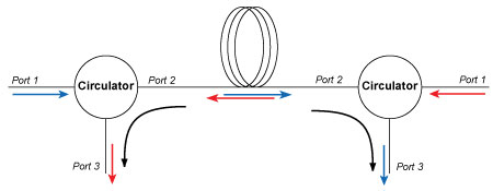
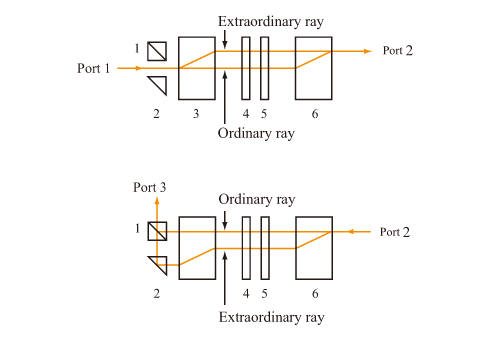
Schematic of operation and (b) application.
Configuration of optical circulator
Figure 3: Configuration of optical circulator. 1: Poparization beam splitter (PBS), 2: reflection prism, 3 and 6: Birefringence crystal, 4: Faraday rotator, 5: half-wave plate

The application of Optical Circulator
An optical circulator is frequently used for an optical time domain reflectometer (OTDR), an optical add-drop multiplexer (OADM) and a dense wavelength devision multiplexing (DWDM) network using an FBG, and a pulse stretcher, a pulse compressor, and a disprersion compensator using a chirped FBG. Optical Circulators can be used to achieve bi-directional transmission over a single fiber. Because of its high isolation of the input and reflected optical powers and its low insertion loss, optical circulators are widely used in advanced communication systems and fiber-optic sensor applications.

Read more related articles :

Friday, September 20, 2013

DWDM & CWDM Solutions


In today’s world of intensive communication needs and requirements, “fiber optic cabling” has become a very popular phrase.  In the field of telecommunications, data center connectivity and ,video transport, fiber optic cabling is highly desirable for today’s communication needs due to the enormous bandwidth availability, as well as reliability, minimal loss of data packets, low latency and increased security.  Since the physical fiber optic cabling is expensive to implement for each individual service, using a Wavelength Division Multiplexing (WDM) for expanding the capacity of the fiber to carry multiple client interfaces is a highly advisable.  WDM is a technology that combines several streams of data/storage/video or voice protocols on the same physical fiber-optic cable by using several wavelengths (frequencies) of light with each frequency carrying a different type of data. With the use of optical amplifiers and the development of the  OTN  (Optical Transport Network) layer equipped with FEC (Forward Error Corection), the distance of the fiber optical communication can reach thousands of Kilometers without the need for regeneration sites.

DWDM vs. CWDM
DWDM (Dense Wavelength Division Multiplexing) is a technology allowing high throughput capacity over longer distances commonly ranging between 44-88 channels/wavelengths and transferring data rates from 100Mbps up to 100Gbps per wavelength. Each wavelength can transparently carry wide range of services such as FE/1/10/40/100GBE, OTU2/OTU3/OTU4, 1/2/4/8/10/16GB FC,STM1/4/16/64, OC3/OC12/OC48/OC-192, HD/SD-SDI and CPRI.  The channel spacing of the DWDM solution is defined by the ITU.xxx (ask Omri) standard and can range from 25Ghz, 50GHz and 100GHz which is the most widely used today. Figure – 1 shows a DWDM spectral view of 88ch with 50GHz spacing.
50GHz spacing 88 DWDM channels/wavelengths
Figure -1: Spectral view of 50GHz spacing 88 DWDM channels/wavelengths
DWDM systems can provide up to 96 wavelengths (at 50GHz) of mixed service types, and can transport to distances up to 3000km by deploying amplifiers, as demonstrated in figure 2) and dispersion compensators thus increasing the fiber capacity by a factor of x100.  Due to its more precise and stabilized lasers, the DWDM technology tends to be more expensive at the sub-10G rates, but is a more appropriate solution and is dominating for 10G service rates and above providing large capacity data transport and connectivity over long distances at affordable costs. The DWDM solution today is often embedded with ROADM (Reconfigurable Optical Add Drop Multiplexer) which enables the building of flexible remotely managed infrastructure in which any wavelength can be added or dropped at any site. An example of DWDM equipment is well demonstrated by PL-1000, PL-1000GM, PL-1000GT, PL-1000RO, PL-2000 and PL-1000TN by DK Photonics Networks.
DWDM solution
Figure-2 Optical amplifier used in DWDM solution to overcome fiber attenuation and increase distance
CWDM (Coarse Wavelength Division Multiplexing) proves to be the initial entry point for many organizations due to its lower cost.  Each CWDM wavelength typically supports up to 2.5Gbps and can be expanded to 10Gbps support.  This transfer rate is sufficient to support GbE, Fast Ethernet or 1/2/4/8/10G FC, STM-1/STM-4/STM-16 / OC3/OC12/OC48, as well as other protocols.  The CWDM is limited to 16 wavelengths and is typically deployed at networks up to 80Km since optical amplifiers cannot be used due to the large spacing between channels. An example of this equipment is well demonstrated by PL-400, PL-1000E and PL-2000 by DK Photonics Networks.
It is important to note that the entire suite of DK Photonics’ equipment is designed to support both DWDM and CWDM technology by using standards based pluggable optical modules such as SFP, XFP and SFP+. The technology used is carefully calculated per project and according to customer requirements of distance, capacity, attenuation and future needs. DK Photonics also provides migration path from CWDM to DWDM enabling low entry cost and future expansion that can be viewed in the DWDM over CWDM technology page

WDM Installation
For designing and implementing a WDM network, there is a need to know some basic information regarding the infrastructure such as fiber type, attenuation of fiber, distance of fiber, network topology, service type, rate and connectivity. Based on this information, calculation of the optical link budget, OSNR (Optical Signal Noise Ratio) and dispersion can be performed in order to provide reliable, error free layer-1 optical solution.
DK Photonics’ WDM diversified equipment portfolio can provide either CWDM or DWDM solution for 4 wavelengths or 88 wavelengths ranging from few km to thousands of km and fit to the exact customer network needs. The network can be a point-to-point, linear add/Drop or ring Topology with passive Mux/DeMux or ROADM based infrastructure.
The WDM equipment serves as a demarcation point and is installed behind the Ethernet switch, router fiber channel SAN Fabric or SDH/SONET ADM coloring the fiber into different spectral wavelengths and multiplexing the rates fully isolated from each other over the same fiber to the remote site.  This allows transmission of multiple channels of different services and rates of data over the same fiber utilizing the fiber resources agnostically to the service type and rate.
The WDM technology can be applied to multiple applications such as connecting building service agnostic optical layer backbone,  data centers connectivity, Video broadcast, LTE fiber, cloud computing backbone, increasing existing fiber bandwidth and spectral efficiency.
Figure 3 shows the main traditional and emerging CWDM and DWDM technology applications which keep  growing along with the rise of the cloud computing and CSP (Content Service Providers) as well as Smart phones and video applications causing constant increase  to the WDM technology deployment and new capacities such as 100G.
Main CWDM and DWDM technology applications
Figure 3 – Main CWDM and DWDM technology applications
DK Photonics’ WDM products designed for easy and fast implementation take up minimal space and use least power, thus providing the highest integration level of CWDM and DWDM networks in the smallest 1U footprint, while providing high ROI. Additionally, the CWDM DWDM optical network is managed remotely with either DK Photonics’ Light Watch NMS/EMS or the imbedded web based management system as well as via any 3rd party SNMP tool.
Read more related articles :
Filter-based WDM          CWDM            Mini CWDM Module       DWDM

Fiber Optic Sensors Global Market Forecast


According to ElectroniCast, the combined use of Continuous Distributed and Point fiber optics sensors will reach $3.98 Billion in 2017…
ShenzhenSeptember 20, 2013  -- ElectroniCast Consultants, a leading market/technology forecast consultancy, today announced the release of their market forecast and analysis of the global consumption Fiber Optic Point Sensors and Continuous Distributed Fiber Optics Sensor system links.
According to ElectroniCast, during the 2012-2017 timeline, the consumption value will grow at an impressive average annual rate of 20.3% from $1.58 billion to $3.98 billion.  Market forecast data refers to consumption (use) for a particular calendar year; therefore, this data is not cumulative data.
Monitoring and data transmission using fiber optic sensors and optical fiber in cabling is now commonplace in various applications, via intrinsic fiber optic sensors or extrinsic fiber optic sensors.  With an intrinsic sensor, one or more of the sensing/measuring quantity or physical properties (measurand) of the optical fiber passes through or inside the optical fiber and therefore experiences a change.  Extrinsic sensing takes place in a region outside of the optical fiber and the optical fiber acts as a transmission media of light to and from (linking) the sensing interface.
Fiber optic sensor technology has experienced impressive growth since ElectroniCast first started providing market and technology analysis of the subject since the early 1980s.  In fact their analysts were tracking the various advanced photonic technologies, since 1976.
DATA FIGURE
According to ElectroniCast, the consumption value of fiber optic sensors (Continuous Distributed + POINT) will grow at an impressive average annual rate of 20.3% from $1.58 billion to $3.98 billion.
Fiber Optic Sensor
Fiber Optic Sensor
DK Photonics – www.dkphotonics.com  specializes in designing and manufacturing of high quality optical passive components mainly for telecommunication, fiber sensor and fiber laser applications,such as WDM, FWDM, CWDM, DWDM, OADM, Circulator, Isolator, PM Circulator, PM Isolator, Fused Coupler, Fused WDM, Collimator, and Polarization Maintaining Components, Pump Combiner, High power isolator, Patch Cord and all kinds of connectors.