Wednesday, May 17, 2017

WDM And The Modules Based On It: The Need Of The Hour

In fiber-optic world of communication, wavelength-division multiplexing or WDM is an innovation which multiplexes various optical transporter signals onto a solitary optical fiber by utilizing distinctive wavelengths, that is the shades of the laser light. This system empowers bidirectional interchanges in more than one strand of fiber, and also increases the limits and domains of it. The term wavelength-division multiplexing is generally connected to an optical transporter, which is normally depicted by its wavelength, though recurrence division multiplexing is commonly applied to a radio bearer which is all the more of a frequently portrayer by recurrence. This is a simple convention since wavelength and recurrence convey a similar data.
How a WDM system works:
A WDM framework utilizes a multiplexer at the transmitter to combine the few signs and a demultiplexer at the collector to part them separated. Hence, WDM Mux and DeMux Modules are made to be used with the correct kind of fiber as it is conceivable to have a gadget that does both all the while, and can work as an optical add-drop multiplexer. The optical filtering gadgets utilized have ordinarily been etalons or to say, stable solid-state single-frequency Fabry–Pérot interferometers in the form of a thin-film-covered optical glass.
Need of WDM Multiplexing:
Since the physical fiber optic cabling is costly to actualize for every single company independently, its ability development by utilizing a Wave Division Multiplexing (WDM) is the need of the hour. WDM innovation was created to extend limits of single fiber systems can give. A WDM framework utilizes a Multiplexer at the transmitter to join a few wavelengths together; thus each one conveys diverse flag and signals via a demultiplexer at the recipient to make them separated. Both Mux and Demux are latent parts of the circuit, as their requirement of power is nil.
Types of WDM available:
These days there are a few sorts of institutionalized WDM in availibility:
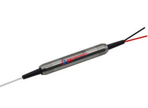
  • General WDM, for example, 980/1550 WDM, 1310/1550 WDM.
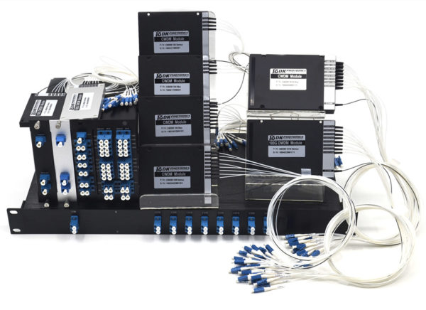
  • CWDM incorporates CWDM mux/demux module and CWDM OADM module. The normal setup of CWDM mux/demux module is 2CH, 4CH, 8CH, 16CH, 18CH CWDM mux/demux module. Single fiber or double fiber association for CWDM Mux/demux are accessible.
  • DWDM incorporates 50GHz, 100GHz, 200GHz DWDM mux/demux module and DWDM OADM module. The normal arrangement is 2CH, 4CH, 8CH, 16 CH, 32CH, 40CH channels.
  • They are accessible as Plastic ABS module tape, 19'' rack mountable box or standard LGX box. What's more, regardless of what sort of connectors, as FC, ST, SC, LC and so on, all is available on DK Photonics, and they additionally can blend connector on one gadget. DK Photonics Technology Limited is one of the main organizations in outlining and assembling of fantastic optical inactive parts primarily for media transmission, fiber sensor and fiber laser applications. Headquarter and manufacturing plant is situated in Shenzhen of China. Savvy, best quality and best administration are forever their objective. So if you have any requirement regarding the WDM or any of the devises based on it, DK Photonics is the reliable and trusted brand!

Tuesday, May 9, 2017

Two Types Of Polarization Beam Combiners & Splitters

Polarizing Beam combiners / splitters are the devices used to combine two polarized light signals or split single non-polarized light into two polarized parts. These combiners and splitters are designed and developed to split light beams by deploying the polarization state and not by wavelength or intensity.
The polarizing beam splitters / combiners typically have 0° or 45° angle of incidence and a 90° division between the beams; this generally depends on the configuration. There are two types of Polarization beam combiners and splitters; these are described below:
  1. Incoherent Polarization Combining / Splitting
The Incoherent combining or splitting is the simpler variant and the basic technique. In this method, the resulted beams of two broad area laser diodes are sent onto a thin-film polarizer so as to reflect one of the beams while transmit the other; both of these beams then propagate in the same direction. As a result, one attains an unpolarized beam (with the combined optical power of the input beams) and the same beam quality. Consequently, the brightness gets nearly doubled.
This technique is often used for any-a-applications, for instance, end-pumping of a solid state laser with an increased power. However, the technique is not suitable for power scaling.
  1. Coherent Polarization Combining / Splitting
With coherent beam combining or splitting it is viable to attain a linear polarized state in the output, if two mutually coherent beams are combined. If two ports have the equal input powers, the output polarization would be typically rotated by 45° -depending on the polarization direction of any of the input beams.
Also, the coherent polarization combining can be repeated several times because of the linear output polarization. Thereby, this technique is suitable for power scaling.
A polarization beam combiner and splitter is often used in photonics instrumentation, optics and semiconductors to transmit p-polarized light while reflecting s-polarized light. These hold a world of worth when it comes to optics, telecommunication and fiber applications, and make the working effective as well as effortless.

Monday, May 8, 2017

Learning the Different Coating Stripping Methods

The cladding power stripper also referred to as the multimode optical power stripper is designed for amplifier applications and high power fiber laser. It is an ideal device  for ASE, residual pump power stripping, core modes that have escaped from double cladding fibers inner cladding while ensuring preservation of single power minimal degradation and beam quality (M2). Single power that is reflected into the inner cladding may also be stripped out too.  The handling capability of the stripping power goes to 800W or at times may be even higher
Stripping the Coating
The fibers that most reputable companies supply all come with a standard  acrylate single layer coating or, in some such as the high power products, a coating that is high temperature enduring. In comparison to dual layer coatings, the coatings that are single layer are more brittle and smooth. The coating can be removed readily using the conventional tools for fiber stripping such as the Fitel S-210 Clauss or CFS-1 for 125 μm cladding diameter fiber or for larger cladding diameters the Clauss No Nik stripper is used. For fibers whose outer diameter is non-standard, it is recommended that an adjustable stripper is used.  Thermal strippers such as those that are attached to the Schleuniger FiberStrip 7030 or the Vytran FFS-2000 can be used for all fiber in a safe way.
Alternatively, chemical stripping of fibers can be done using an appropriate solvent. For example, the coating can be exposed for one minute to sulfuric acid at 120°C sulfuric acid. Before the fiber is dipped into the liquid, the tip should be sealed with a drop of glue of 2 mm in diameter or through the end fiber hole collapsing using a fusion splicer.  It is worth noting that most glue types are dissolved in this acid, but epoxies that are two-component such as the Epotek ND353 tends to dissolve in a slower manner than the coating.
It is also possible to obtain chemical stripping through application on the fiber tip, of paint stripper. The paint stripper is usually in the form of a gel so as to reduce the occurrence of out-gassing and can be applied easily using a small brush. After a minute or so, the coating becomes soft and is removed easily using a lens tissue. It is worth noting that paint stripper typically contains dichloromethane (CH2Cl2) and as such there may be restrictions by local regulations to use it. For lower quality and faster stripping, another option would be to use a normal cigarette lighter to burn the coating off. However, the fiber may end up becoming brittle hence not the best choice for stripping.