ElectroniCast Consultants, a leading market/technology forecast consultancy, today announced the release of their market forecast and analysis of the global consumption of Fiber Optic Sensors.
According to the study, the combined use of Distributed and Point (local) fiber optics sensors reached $3.38 Billion last year (2016), and the worldwide value is forecast to reach $5.98 Billion in 10-years (2026). Market forecast data in this study report refers to consumption (use) for a particular calendar year; therefore, this data is not cumulative data.
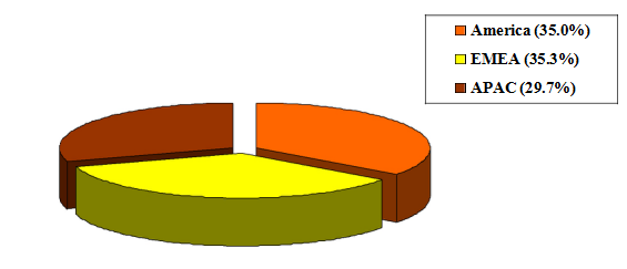
Both the American region and the EMEA region held similar market share in the overall (distributed- and point-types) fiber optic sensor value last year. The Europe, Middle East, Africa region (EMEA) held a very slight lead in relative market (value) share last year; however, the Asia Pacific region (APAC) is projected to take-over the leadership position during the forecast period.
The EMEA region is forecast to have a strong role in the use of distributed fiber optic systems, driven by the region’s use of systems in aviation, as well as in the
Petrochemical, Natural Resources, Energy/Utility application categories.
In terms of fiber optic point sensors, the American region is forecast to maintain the market share lead throughout the 1st-half of the forecast period (2016-2021), mostly led by the use of Fiber Optic Gyros (FOGs) in the Military/Aerospace application category. The consumption values are based on the end-user application and the end-user region.
FOGs held a 65 percent market share of the worldwide Point fiber optic sensor consumption value in 2016. “All regions, thanks mainly to increases in the use in aviation and military critical mission applications (Unmanned Aerial Vehicle/UAV and missile guidance, navigation, north finding/tracking, robotics, aviation and aeronautics and other) are forecast to show impressive increase consumption quantity (volumes) and values for the FOG systems,” said Stephen Montgomery, Director of the Fiber Optics Components group at ElectroniCast Consultants.
The market forecast of the Distributed Sensors is segmented by the following applications:
- Manufacturing Process/Factory
- Civil Engineering/Construction (buildings, bridges, tunnels, etc)
- Military/Aerospace/Security
- Petrochemical/Energy/Utilities/Natural Resources
- Biomedical/Science
- Mechanical Strain
- Temperature
- Pressure
- Chemical, Gas, Liquid
- Vibration, Acoustic, Seismic
- Displacement, Acceleration, Proximity
- Electric, Current and Magnetic Field - Fiber Optic Sensors
- Rotation (such as Fiber Optic Gyroscopes: FOGs)
According to ElectroniCast, the combined use of Distributed and Point fiber optics sensors reached $3.38 Billion in 2016…
Continuous Distributed and Point Fiber Optic Sensor
Global Consumption ($3.38 Billion in 2016)
Source: ElectroniCast Consultants
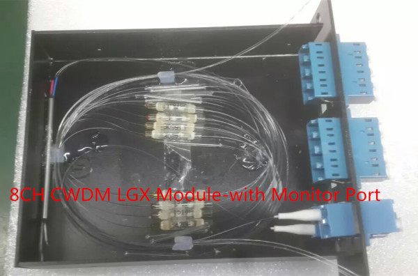
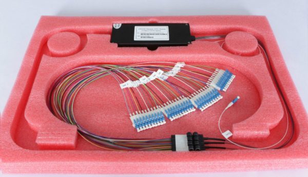
Tags: CWDM Multiplexer, DWDM Multiplexer,19" rack mount chassis CWDM, CWDM MUX/DEMUX Module, LGX CWDM Module,8CH CWDM Module, 16CH CWDM Module, 100GHz DWDM Mux/Demux, 200GHz DWDM Mux/Demux
DK Photonics – www.dkphotonics.com specializes in designing and manufacturing of high quality optical passive components mainly for telecommunication, fiber sensor and fiber laser applications,such as 1064nm High Power Isolator,1064nm Components, PM Components, (2+1)x1 Pump Combiner,Pump Laser Protector,Mini-size CWDM,100GHz DWDM,Optical Circulator,PM Circulator,PM Isolator,Fused Coupler,Mini Size Fused WDM.