Monday, May 25, 2015

Do you know these about CWDM Multiplexer and DWDM Multiplexer?

Do you know these about CWDM Multiplexer and DWDM Multiplexer?
Wavelength division multiplexing (WDM) is a technology or technique modulating numerous data streams, i.e. optical carrier signals of varying wavelengths (colors) of laser light, onto a single optical fiber. The goal of WDM is to have a signal not to interfere with each other. It is usually used to make data transmission more efficiently. It has also been proven more cost effective in many applications, such as WDM network applications, broadband network application and fiber to the home (FTTH) applications and so on. According to channel spacing between neighbored wavelengths, there are two main types of WDM, including Coarse WDM (CWDM) and Dense WDM (DWDM). Though both of them belong to WDM technology, they are quite different. Then, what are the differences between them? This paper will give you the answer.
Definition of CWDM
CWDM is a method of combining multiple signals on laser beams at various wavelengths for transmission along fiber optic cables, such that the number of channels is fewer than in DWDM but more than in standard WDM. “Course” means the channel spacing is 20nm with a working channel passband of +/-6.5nm from the wavelengths center. From 1270nm to 1610nm, there are 18 individual wavelengths separated by 20nm spacing.
Definition of DWDM
DWDM is a technology that puts data from different sources together on an optical fiber, with each signal carried at the same time on its own separate light wavelength. “Dense” refers to the very narrow channel spacing measured in Gigahertz (GHz) as opposed to nanometer (nm). DWDM typically uses channel spacing of 100GHz with a working channel passband of +/-12.5GHz from the wavelengths center. It uses 200GHz spacing essentially skipping every other channel in the DWDM grid. And it has also gone one step further using an Optical Interleaver to get down to 50GHz spacing doubling the channels’ capacity from 100GHz spacing.
CWDM vs DWDM
According to the content above, you will find some small differences between them. 16CH CWDM Module is defined by wavelengths and has wide range channel spacing. DWDM is defined by frequencies and has narrow channel spacing. What’s more, what other differences do they have?
Capacity of Data
In fiber optic network system, DWDM system could fit more than 40 different data streams in the same amount of fiber used for two data streams in a CWDM system. In some cases, CWDM system can perform many of the same tasks compared to DWDM. Despite the lower transmission of data through a CWDM system, these are still viable options for fiber optic data transmission.
Cost of Cable
CWDM system carries less data, but the cabling used to run them is less expensive and less complex. A DWDM system has much denser cabling and can carry a significantly larger amount of data, but it can be cost prohibitive, especially where there is necessary to have a large amount of cabling in an application.
Long-haul or Short-haul Transmission
DWDM system is used for a longer haul transmission through keeping the wavelengths tightly packed. It can transmit more data over a significantly larger run of cable with less interference. However, CWDM system cannot travel long distances because the wavelengths are not amplified, and therefore CWDM is limited in its functionality over longer distances. If we neeed to transmit the data over a very long range, DWDM system solution may be the best choice in terms of functionality of the data transmission as well as the lessened interference over the longer distances that the wavelengths must travel. As far as cost is concerned, when required to provide signal amplification about 100 miles (160km), CWDM system is the best solution for short runs.
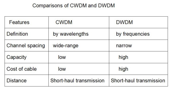
According to the content above, maybe you have already understood some differences between CWDM and DWDM by the comparision of them from definition, capacity, cable cost and transmission distance etc. And here is also a figure of comparisons between CWDM and DWDM which may help you to consolidate your understanding of this paper.
CWDM Multiplexer and DWDM Multiplexer
Tags: 19" rack mount chassis CWDM, ABS plastic box, CWDM MUX/DEMUX Module,  LGX CWDM Module,8CH CWDM Module, 16CH CWDM Module

Thursday, May 21, 2015

Saving Your Fibers By Using CWDM Or DWDM Multiplier

Using a WDM(Wavelength Division Multiplexing) for expanding the capacity of the fiber to carry multiple client interfaces is a highly advisable way as the physical fiber optic cabling is not cheap. As WDM widely used you must not unfamiliar with it, it is a technology that combines several streams of data/storage/video or voice protocols on the same physical fiber-optic cable, by using several wavelengths (frequencies) of light with each frequency carrying a different type of data.
Two types of WDM architecture available: Coarse Wavelength Division Multiplexing (CWDM) and Dense Wavelength Division Multiplexing (DWDM). CWDM/DWDM multiplexer and demultiplexer and OADM (Optical Add-Drop Multiplexer) are common fit in with Passive. With the use of optical amplifiers and the development of the OTN (Optical Transport Network) layer equipped with FEC (Forward Error Correction), the distance of the fiber optical communication can reach thousands of Kilometers without the need for regeneration sites.
16-Ch CWDM Mux/Demux Module
CWDM
Each CWDM wavelength typically supports up to 2.5Gbps and can be expanded to 10Gbps support. The CWDM is limited to 16 wavelengths and is typically deployed at networks up to 80Km since optical amplifiers cannot be used due to the large spacing between channels. CWDM uses a wide spectrum and accommodates eight channels. This wide spacing of channels allows for the use of moderately priced optics, but limits capacity. CWDM is typically used for lower-cost, lower-capacity, shorter-distance applications where cost is the paramount decision criteria.
The CWDM Mux/Demux (or CWDM multiplexer/demultiplexer) is often a flexible plug-and-play network solution, which helps insurers and enterprise companies to affordably implement denote point or ring based WDM optical networks. CWDM Mux/demux is perfectly created for transport PDH, SDH / SONET, ETHERNET services over WDM, CWDM and DWDM in optical metro edge and access networks. CWDM Multiplexer Modules can be found in 4, 8 and 16 channel configurations. These modules passively multiplex the optical signal outputs from 4 too much electronic products, send on them someone optical fiber and after that de-multiplex the signals into separate, distinct signals for input into gadgets across the opposite end for your fiber optic link.
Typically CWDM solutions provide 8 wavelengths capability enabling the transport of 8 client interfaces over the same fiber. However, the relatively large separation between the CWDM wavelengths allows expansion of the CWDM network with an additional 44 wavelengths with 100GHz spacing utilizing DWDM technology, thus expanding the existing infrastructure capability and utilizing the same equipment as part of the integrated solution.
100GHz 8-Ch DWDM Mux/Demux Module
DWDM
DWDM is a technology allowing high throughput capacity over longer distances commonly ranging between 44-88 channels/wavelengths and transferring data rates from 100Mbps up to 100Gbps per wavelength.
DWDM systems pack 16 or more channels into a narrow spectrum window very near the 1550nm local attenuation minimum. Decreasing channel spacing requires the use of more precise and costly optics, but allows for significantly more scalability. Typical DWDM systems provide 1-44 channels of capacity, with some new systems, offering up to 80-160 channels. DWDM is typically used where high capacity is needed over a limited fiber resource or where it is cost prohibitive to deploy more fiber.
The DWDM multiplexer/demultiplexer Modules are made to multiplex multiple DWDM channels into one or two fibers. Based on type CWDM Mux/Demux unit, with optional expansion, can transmit and receive as much as 4, 8, 16 or 32 connections of various standards, data rates or protocols over one single fiber optic link without disturbing one another.
Ultimately, the choice to use CWDM or DWDM is a difficult decision, first we should understand the difference between them clearly.
CWDM vs DWDM
CWDM scales to 18 distinct channels. While, DWDM scales up to 80 channels (or more), allows vastly more expansion. The main advantage of CWDM is the cost of the optics which is typically 1/3rd of the cost of the equivalent DWDM optic. CWDM products are popular in less precision optics and lower cost, less power consumption, un-cooled lasers with lower maintenance requirements. This difference in economic scale, the limited budget that many customers face, and typical initial requirements not to exceed 8 wavelengths, means that CWDM is a more popular entry point for many customers.
Buying CWDM or DWDM is driven by the number of wavelengths needed and the future growth projections. If you only need a handful of waves and use 1Gbps optics, CWDM is the way to go. If you need dozens of waves, 10Gbps speeds, DWDM is the only option.

Wednesday, May 20, 2015

DK Photonics Makes Top End Optical Passive Components Available

China, 19th May, 2015: Optical passive components available at DK Photonics are significant in a number of industries such as telecommunication applications, fiber laser, etc. The DK Photonics ensures that the quality of these is high and the prices are competitive. There are many fields which require such merchandises and hence, this Company can be considered for their supply.
Some of their products which are said to have a large customer base are their high power isolators and PM components. These are made to provide optimized performance under any conditions. The fact that the Company has been in the production of these for the last eight years is another thing worth a mention. Apart from this, they even offer their services to all those who wish to know more about their usage. Be it industries or research scientists, the DK Photonics welcomes any queries related to their field.
The customer service team aims at providing solutions to all their patrons in a timely manner. Most of the reviews have been positive when it comes to delivery, after sales service and product quality. DK Photonics is also looking for investors who wish to back them in their future endeavors. Interested people may contact them to know more.
The DK Photonics says, “We have a team of experts who are passionate about making these components of top quality. Our customers range from telecommunication and fiber laser companies to research centers. Some of the popular products include the LGX CWDM Module, 16 channel CWDM, 100GHz DWDM Module and CWDM Multiplexer. Based in Guangdong, China, DK Photonics Technology Ltd is one of the well known names in the field.
To obtain more information about the products, visit http://www.dkphotonics.com/.
About DK Photonics

The DK Photonics claims that they even provide customized solutions to their patrons. Those industries who wish their products to be distinctive can contact them for the same. The team mentions that they have passed the ISO9001 quality tests and hence, there is no compromise in this aspect.

Tuesday, May 12, 2015

Ultrafast laser pulses induce atoms in gold nanodisks to vibrate

In a study that could open doors for new applications of photonics from molecular sensing to wireless communications, Rice University scientists have discovered a new method to tune the light-induced vibrations of nanoparticles through slight alterations to the surface to which the particles are attached.
In a study published online this week in Nature Communications, researchers at Rice’s Laboratory for Nanophotonics (LANP) used ultrafast laser pulses to induce the atoms in gold nanodisks to vibrate. These vibrational patterns, known as acoustic phonons, have a characteristic frequency that relates directly to the size of the nanoparticle. The researchers found they could fine-tune the acoustic response of the particle by varying the thickness of the material to which the nanodisks were attached.
“Our results point toward a straightforward method for tuning the acoustic phonon frequency of a nanostructure in the gigahertz range by controlling the thickness of its adhesion layer,” said lead researcher Stephan Link, associate professor of chemistry and in electrical and computer engineering.
Rice University researchers (clockwise from front) Man-Nung Su, Wei-Shun Chang and Fangfang Wen discovered a new method to tune the light-induced vibrations of nanoparticles through slight alterations to the surface to which they are attached.
Light has no mass, but each photon that strikes an object imparts a miniscule amount of mechanical motion, thanks to a phenomenon known as radiation pressure. A branch of physics known as optomechanics has developed over the past decade to study and exploit radiation pressure for applications like gravity wave detection and low-temperature generation.
Link and colleagues at LANP specialize in another branch of science called plasmonics that is devoted to the study of light-activated nanostructures. Plasmons are waves of electrons that flow like a fluid across a metallic surface.
When a light pulse of a specific wavelength strikes a metal particle like the puck-shaped gold nanodisks in the LANP experiments, the light energy is converted into plasmons. These plasmons slosh across the surface of the particle with a characteristic frequency, in much the same way that each phonon has a characteristic vibrational frequency.
The study’s first author, Wei-Shun Chang, a postdoctoral researcher in Link’s lab, and graduate students Fangfang Wen and Man-Nung Su conducted a series of experiments that revealed a direct connection between the resonant frequencies of the plasmons and phonons in nanodisks that had been exposed to laser pulses.
“Heating nanostructures with a short light pulse launches acoustic phonons that depend sensitively on the structure’s dimensions,” Link said. “Thanks to advanced lithographic techniques, experimentalists can engineer plasmonic nanostructures with great precision. Based on our results, it appears that plasmonic nanostructures may present an interesting alternative to conventional optomechanical oscillators and high power isolator
Chang said plasmonics experts often rely on substrates when using electron-beam lithography to pattern plasmonic structures. For example, gold nanodisks like those used in the experiments will not stick to glass slides. But if a thin substrate of titanium or chromium is added to the glass, the disks will adhere and stay where they are placed.
“The substrate layer affects the mechanical properties of the nanostructure, but many questions remain as to how it does this,” Chang said. “Our experiments explored how the thickness of the substrate impacted properties like adhesion and phononic frequency.”
Link said the research was a collaborative effort involving research groups at Rice and the University of Melbourne in Victoria, Australia.
“Wei-Shun and Man-Nung from my lab did the ultrafast spectroscopy,” Link said. “Fangfang, who is in Naomi Halas’ group here at Rice, made the nanodisks. John Sader at the University of Melbourne, and his postdoc Debadi Chakraborty calculated the acoustic modes, and Yue Zhang, a Rice graduate student from Peter Nordlander’s group at Rice simulated the optical/plasmonic properties. Bo Shuang of the Landes’ research group at Rice contributed to the analysis of the experimental data.”
The research was supported by the Robert A. Welch Foundation and the Department of Defense’s Multi-University Research Initiative. Additional co-authors include Zhang, Shuang, Nordlander and Halas, all of Rice; and Chakraborty and Sader, both of the University of Melbourne in Victoria, Australia.
About DK Photonics
DK Photonics – www.dkphotonics.com  specializes in designing and manufacturing of high quality optical passive components mainly for fiber laser applications such as 1064nm high power isolator, Cladding Power Stripper, Multimode High Power Isolator, pump combiner,1064nm Band-pass Filter,(6+1)X1 Pump and Signal Combiner, PM Circulator, PM Isolator, optical Coupler. More information, please contact us.

Thursday, May 7, 2015

Polarization Dependent Isolator vs Polarization Independent Isolator

Connectors and other types of optical devices on the output of the transmitter may cause reflection, absorption, or scattering of the optical signal. These effects on the light beam may cause light energy to be reflected back at the source and interfere with source operation. In order to reduce the effects of the interference, an optical isolator is usually used. Optical isolator allows a beam of light to stream through a single one way direction. At the same time, it prevents the light from going back in the opposite direction. According to the polarization characteristics, optical isolators can be divided into two types, including polarization dependent isolator and polarization independent isolator. The polarizer-based module makes a polarization dependent isolator, and the birefringent crystal-based structure makes a polarization independent isolator. You may be very confused about them as you find that there is only a little difference via their names. So, what are they and what are the differences between them? This paper will give you the answer.
Polarization Dependent Isolator
The polarization dependent isolator consists of three parts, an input polarizer , a Faraday rotator, and an output polarizer. Light traveling in the forward direction becomes polarized vertically by the input polarizer. The Faraday rotator will rotate the polarization by 45°. The analyser then enables the light to be transmitted through the isolator.
Polarization-Dependent-Isolator
Light traveling in the backward direction becomes polarized at 45° by the analyser. The Faraday rotator will again rotate the polarization by 45°. This means the light is polarized horizontally. Since the polarizer is vertically aligned, the light will be extinguished.
The picture shows us a Faraday rotator with an input polarizer, and an output analyser. For a polarization dependent isolator, the angle between the polarizer and the analyser, is set to 45°. The Faraday rotator is chosen to give a 45° rotation.
Because the polarization of the source is typically maintained by the system, polarization dependent isolator is widely used in free space optical systems.
Polarization Independent Isolator
The polarization independent isolator also consists of three parts, an input birefringent wedge, a Faraday rotator, and an output birefringent wedge. Light traveling in the forward direction is split by the input birefringent wedge into its vertical (0°) and horizontal (90°) components, called the ordinary ray (o-ray) and the extraordinary ray (e-ray) respectively. The Faraday rotator rotates both the o-ray and e-ray by 45°. This means the o-ray is now at 45°, and the e-ray is at −45°. The output birefringent wedge then recombines the two components.
Polarization-Independent-Isolator
Light traveling in the backward direction is separated into the o-ray at 45, and the e-ray at −45° by the birefringent wedge. The Faraday Rotator again rotates both the rays by 45°. Now the o-ray is at 90°, and the e-ray is at 0°. Instead of being focused by the second birefringent wedge, the rays diverge. The picture shows the propagation of light through a polarization independent isolator.
While polarization dependent isolator allows only the light polarized in a specific direction, polarization independent isolator transmit all polarized light. So it is usually widely used in optical fiber amplifier.
Comparison of Polarization Dependent Isolator and Polarization Independent Isolator
In fact, you have already understood these two types of isolators according to the contents above. We can see their similarities and differences through the comparison of their definition, working principle and applications. Both of them consist of three parts and have a same principle based on Faraday effect. However, to overcome the limitation of polarization dependent isolator, polarization independent isolator has been developed. Regardless of the polarization state of the input beam, the beam will propagate through the isolator to the output fiber and the reflected beam will be isolated from the optical source. If the extinction ratio is important, a polarization dependent isolator should be used with either polarization maintaining fibers or even regular single-mode fibers. If the system has no polarization dependence, a polarization independent isolator will be the obvious choice.
About DK Photonics
DK Photonics – www.dkphotonics.com  specializes in designing and manufacturing of high quality optical passive components mainly for fiber laser applications such as 1064nm high power isolator, Cladding Power Stripper, Multimode High Power Isolator, pump combiner,1064nm Band-pass Filter,(6+1)X1 Pump and Signal Combiner, PM Circulator, PM Isolator, optical Coupler. More information, please contact us.