Sunday, April 21, 2013

What Is an Optical Attenuator?

An optical attenuator decreases the strength of an optical signal passing through it to a fiber optic cable or open air. The intensity of the signal is described in decibels over a specific distance the signal travels. It is the strength, or amplitude of the signal that changes and not the overall waveform or frequency, so the optical signal remains undistorted for use in the desired application. Optical attenuators are often used in optical communication systems, in which the attenuation, also called transmission loss, helps with the long-distance transmission of digital signals. The most common optical attenuator types include fixed and continuously variable attenuators.
Often installed where signals are transmitted from, an optical attenuator can apply the principle of gap loss so the signal intensity is lowered to the optimal level over a given distance. Attenuators installed elsewhere along the optical fiber will not lower the signal strength enough, but some devices utilize signal absorbing or reflecting components to compensate. An optical fiber connector is often attached to the optical attenuator which typically has an adapter with a female configuration. The attenuator itself usually has a cylindrical or even box-like structural shape which determines the type of equipment in which it can be installed.
The fixed variety of optical attenuator, sometimes found in an electronic circuit, does not reflect light signals to reduce their intensity. It is generally used where the transmission of data needs to be highly accurate. The device’s function is determined by the amount of power it can handle in addition to important variables such as performance versus temperature and frequency range. Most optical attenuators utilize resistors, but a variable optical attenuator uses metal semiconductor field effect transistors or other solid state components. Attenuation intensity is adjustable so the signals in a fiber optic communication system can be changed to accommodate fluctuating power levels, protecting the system from damage.
A variable optical attenuator can be mounted on a printed circuit board, or used in test devices such as an optical power meter. Many attenuators are installed in-line with an optical fiber cable in order to adjust the transmitted signal accordingly. They are sold by many retailers and manufacturers online so one can assess their characteristics by reading the product specifications. Aspects to consider include the average and peak power the device can tolerate, how much attenuation it provides, as well as its overall dimensions and the type of environment it can operate in.

Wednesday, April 10, 2013

SC fiber optic connector basic structure


More than a dozen types of fiber optic connectors have been developed by various manufacturers since 1980s. Although the mechanical design varies a lot among different connector types, the most common elements in a fiber connector can be summarized in the following picture. The example shown is a SC connector which was developed by NTT (Nippon Telegraph and Telephone) of Japan.
SC ConnectorA SC Connector Sample

sc connector
SC Connector Structure

Elements in a SC connector

1. The fiber ferrule.
clip_image006_0001SC Connector Fiber Ferrule
SC connector is built around a long cylindrical 2.5mm diameter ferrule, made of ceramic (zirconia) or metal (stainless alloy). A 124~127um diameter high precision hole is drilled in the center of the ferrule, where stripped bare fiber is inserted through and usually bonded by epoxy or adhesive. The end of the fiber is at the end of the ferrule, where it typically is polished smooth.
2. The connector sub-assembly body.
The ferrule is then assembled in the SC sub-assembly body which has mechanisms to hold the cable and fiber in place. The end of the ferrule protrudes out of the sub-assembly body to mate with another SC connector inside a mating sleeve (also called adapter or coupler).
3. The connector housing
Connector sub-assembly body is then assembled together with the connector housing. Connector housing provides the mechanism for snapping into a mating sleeve (adapter) and hold the connector in place.
4. The fiber cable
Fiber cable and strength member (aramid yarn or Kevlar) are crimped onto the connector sub-assembly body with a crimp eyelet. This provides the strength for mechanical handing of the connector without putting stress on the fiber itself.
5. The stress relief boot.
Stress relief boot covers the joint between connector body and fiber cable and protects fiber cable from mechanical damage. Stress relief boot designs are different for 900um tight buffered fiber and 1.6mm~3mm fiber cable.

Sunday, April 7, 2013

Different Types And Applications: Fiber Optic Attenuators


A fiber optical attenuator is a fiber-coupled device used to reduce or balance the power (the power level of an optical signal, either in free space or in an optical fiber) of the light transmitted from one device to another device. Fiber optic attenuators are designed to use with various kinds of fiber optic connectors. The basical types of optical attenuators are fixed, step-wise variable, and variable fiber optic attenuator. Insertion loss and return loss, or back reflection, are collectively referred to as attenuation; total attenuation is called system loss.

Fiber Optic Attenuators provide technicians with a means of adjusting an optical signal level. Attenuators are commonly used in fiber optic communications, either to test power level margins by temporarily adding a calibrated amount of signal loss, or installed permanently to properly match transmitter and receiver levels.

Commonly used fiber optic attenuators are the female to male type, which is also called a plug fiber attenuator. Plug fiber attenuators utilize male/female ceramic ferrule connectors. Fixed value attenuators function at one loss level, while variable attenuators like the variable optical attenuated jumper (VOA) can adjust loss in a range, as by a turning screw. Patch cord attenuators are fibers that combine the functions of the patch cord and attenuator, reducing costs.

Types of fiber optic attenuators:
 1. Female to male plug style optical attenuator (MU, SC, FC, ST, LC) PC& APC polish available;
 2. Flange style fiber optical attenuator;
 3. Adjustable fiber optical attenuator (FC style) Attenuation scale:0~30dB;
 4. IN-Line style fiber optical attenuator.

Wide range variable & inline fiber optic attenuator
The inline fiber optic attenuators are with more accurate attenuation compared with traditional connector type fiber optic attenuators. What is more, the fiber optic attenuator is with a precision screw set, by turing it, the attenuation range can be varied. And this fiber optical attenuator can be with various terminations on the each side of the cable.

Variable Fiber Optic Attenuators
Fixed value fiber optic attenuators can reduce the power of fiber light at a fixed value loss, for example, a 10dB SC fiber optic attenuator will reduce the optical power 10dB and utilize a SC male to female attenuator. Variable fiber optic attenuators (or adjustable fiber optic attenuator) are with adjustable attenuation range. It usually is inline type, the appearance like fiber optic patch cord; it is with an adjustable component in the middle of the device to change the attenuation level to a certain figure. There are also handheld variable fiber optic attenuators; they are used as test equipment, and we have the inline fiber optic attenuators.

Fiber optic attenuator name is based on the connector type (like lc attenuator) and the attenuation level. For example, LC 5dB fiber optic attenuator means this attenuator use LC fiber optic connector and it can reduce the optical fiber power level by 5dB. Commonly used attenuation range is from 1dB to 20Db. Fiber Optic Attenuators are employed in telecommunications networks, local area networks (LAN), and cable television (CATV) systems. They also can be used in fiber optic sensors, testing instruments, and fiber to the home. Compact, environmentally sound, and suffering low return losses, these devices can be embedded into optical fiber networks fitted to the wide variety of industry standard connectors and fibers.

How are Optic Fiber Made?


Many People ask how fiber optics are made. You can’t just use “regular” glass. If you were to make optical fiber from ordinary window glass, the light that you shine through it would have a difficult time traveling more than a few kilometers, let alone the distances necessary for long distance transmission. That’s because ordinary glass contains distortions, discolorations and other impurities that would quickly absorb, reflect, or otherwise disperse light long before it could travel any great distance.
In contrast, because optical fiber is actually made from very pure glass, the light traverses great distances largely unimpeded by impurities and distortions.
Fiber Optic Cable – Light How it Works
To transmit light effectively, fiber optic cable must contain glass of the highest purity. The process of making glass with this level of purity is very demanding, requiring careful control over the materials and processes involved. Yet, the fundamental concept is simple. Essentially, optical fiber is made from drawing molten fiber from a heated glass blank or “preform.” The following provides a more detailed explanation of the three basic steps involved in making optical fiber.
Step #1
Create the Fiber Optic Preform

A preform is a cylindrical glass blank that provides the source material from which the glass fiber will be drawn in a single, continuous strand.
Making a preform involves a chemical process known as Modified Chemical Vapor Deposition (MCVD). This process involves bubbling oxygen through various chemical solutions including germanium chloride (GeC14) and silicon chloride (SiC14).
The bubbling chemicals produce gas that is directed into a hollow, rotating tube made of synthetic silica or quartz. A torch is moved up and down the rotating tube, resulting in very high temperatures that cause the gas to react with oxygen to form silicon dioxide (Si02) and germanium dioxide (Ge02). These two chemicals adhere to the inside of the rotating tube where they fuse together to form extremely pure glass.
Creating the preform takes several hours, after which additional time is required for the glass blank to cool. Once cooled, the glass is tested to ensure that it meets quality standards, especially in terms of index of refraction.
Step #2
Draw Optical Fiber from the Preform
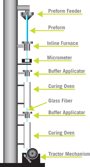
In this step, the finished glass preform is installed at the top of a tower which supports various devices used in the fiber drawing process.
The process begins by lowering one end of the preform into an in-line furnace that produces heat in a range of 3,400 to 4,000 degrees Fahrenheit. As the lower end of the preform begins to melt, it forms a molten glob that is pulled downward by gravity. Trailing behind the glob is a thin strand of glass that cools and solidifies quickly.
The equipment operator threads this glass strand through the remainder of the devices on the tower, which include a number of buffer coating applicators and ultraviolet curing ovens. Finally, the operator connects the fiber to a tractor mechanism.
The tractor device pulls the glass strand from the preform at a rate of 33 to 66 feet per second. The actual speed at which the tractor pulls the strand is dependent upon the feedback information the device receives from a laser micrometer that continually measures the fiber’s diameter.
At the end of the run, the completed fiber is wound onto a spool.
Step # 3
Test the Fiber Optics
The completed optical fiber must undergo a number of tests to determine the quality of the finished product. The following are a few of the assessments involved:
• Refractive index profile
• Fiber geometry inspection, including core, cladding and coating
• Tensile strength • Bandwidth capacity
• Attenuation at different wavelengths
• Chromatic dispersion
• Operating temperature and humidity range

Quality Control in Optical Fiber Production
Various factors influence the quality and purity of the optical fiber produced. These include: Chemical Composition – Achieving optimal ratios of the various chemicals used to create the preform is important for achieving glass purity. This mixture of chemicals also determines the optical properties of the fiber that will be produced from the preform, including coefficient of expansion, index of refraction, and so forth. Gas Monitoring – It is crucial that the gas composition and rate of flow be monitored throughout the process of creating the preform. It is also important that any valves, tubes and pipes that come into contact with the gas be made of corrosion-resistant materials.
Heat and Rotation – The hollow cylinder that is used to create the preform must be heated at the proper temperature and continually rotated to enable the chemicals to be deposited evenly.