Tuesday, October 29, 2013

What is Pump Laser Protector, Where is the Pump Laser Protector use?


The Pump Laser Protector (also called Pump Protection Filters) is a passive component which allows maximum transmission from a discrete fibre-coupled pump laser diode and blocks parasitic signals around the centre wavelength of the laser from being reflected back into the laser.
Pump Laser Protector
Multimode Pump Laser Protector -10~30W
Single-emitter laser diodes are highly regarded for their long term reliability. However, these devices are very sensitive to backward propagating light within the delivery fiber. Backward power imaged onto the diode material, as small as 5% of the pump diode output, can cause accelerated diode degradation and, in the majority of cases, catastrophic failure.That is why we need Pump Laser Protector.
DK Photonics offers filter technology that provides protection to pump diodes under these conditions (up to 50 dB Backward Signal Attenuation). Splicing these filters to the pump output fiber rejects unwanted light before it reaches the diode.
Multimode Pump Protection filters are available for a wide range of standard light emitting diodes. Fiber pigtails are 105/125 micron, with both 0.15 and 0.22 NA cores and 50/125 or 62.5/126 MM fiber available. Operating wavelengths cover the majority of diode laser lines (915 nm, 940 nm, 960 nm and 976) and maximum power handling is 25W without water-cooling.DK Photonics recently released a new type of Pump Laser Protector up to 200W handling power with water-cooling technology. And also have SingleMode Pump Laser Protector with Hi1060 fiber for 976nm fiber laser.
If you do not see a Pump Laser Protector from the standard configurations that meets your needs, we welcome the opportunity to review your desired specification and quote a filter best suited to your application. Different pump/rejection wavelengths or fiber pigtail can be accommodated.
DK Photonics – www.dkphotonics.com specializes in designing and manufacturing of high quality optical passive components mainly for telecommunication, fiber sensor and fiber laser applications,such asDK Photonics' promotion products including:High Power Isolator,1064nm Components,PM Components,Pump Combiner,Pump Laser Protector,which using for fiber laser applications.Also have Mini-size CWDM, Optical Circulator, PM Circulator,PM Isolator, Fused Coupler,Mini Size Fused WDM.More information,please contact us.

Wednesday, October 23, 2013

Introduction for CWDM MUX+DEMUX Module 8/16 Channels Dual Fiber with 1U 19 Rack Mount Box


Why do we choose CWDM MUX/DEMUX solution?
CWDM Mux/Demux is a flexible, low-cost solution that enables the expansion of existing fiber capacity. The CWDM Mux/Demux lets operators make full use of available fiber bandwidth in local loop and enterprise architectures. DK Photonics’ CWDM Mux/Demux is a universal device capable of combining up to 18 optical signals into a fiber pair or single fiber. It is designed to support a broad range of architectures, ranging from scalable point-to-point links to two fiber-protected rings. The important advantage of CWDM solution is the cost of the optics which is typically 1/3rd of the cost of the equivalent DWDM optics.
Description:
DK Photonics CWDM MUX+DEMUX Module 8/16 Channels (Dual Fiber) with 1U 19 Rack Mount Box utilize thin film coating technology and proprietary design of non-flux metal bonding micro optics packaging. Our 8CH CWDM Mux and Demux dual fiber 1U 19 Rack Mount Box support ITU-T G.694.2 wavelengths between 1270nm to 1610nm in 20nm increments. (Note: The ITU standard specifies the exact center of 8/16CH CWDM Mux and Demux dual fiber 1U 19 Rack Mount Box wavelength as 1531nm, 1591nm, 1611nm, etc. However, for clarity (and to comply with general industry conventions) the text in this data sheet refers to these wavelengths as 1530nm, 1590nm, 1610nm, etc.) 8/16 Channel CWDM Mux and Demux dual fiber 1U 19 Rack Mount Box are protocol and rate transparent allowing different services up to 10Gbps to be transported across the same fiber link. It allows for any protocol to be transported over the link, as long as it is at a specific wavelength (i.e. T1 over fiber at 1570nm transported alongside 10Gbps Ethernet at 1590nm). This allows for long-term future proofing of the networking infrastructure because the multiplexers simply refract light at any network speed, regardless of the protocol being deployed.
Our CWDM Mux/Demux can support up to 18 wavelengths between 1270nm to 1610nm in 20nm increments when com fiber is ITU-T G.694.2 , however if com fiber is ITU-T G.652, we recommend adopt 1270nm and 1290nm instead of 1390nm and 1509nm because of water peak loss.
DK Photonics’ provides a complete portfolio of CWDM Mux Demux and Optical Add Drop Multiplexer (OADM) units to suit all applications such as:- Gigabit & 10G Ethernet, SDH/SONET, ATM, ESCON, Fibre Channel, FTTx and CATV.
8/16 channel CWDM MUX+DEMUX in point to point application
Key Features
  • Up to 18 channels over 2 fibers
  • MUX and DEMUX combined 1U
  • Optical interfaces support all protocols from 30Mbps to 10Gbps, including OC-3/STM-1, OC-12/STM-4, OC-48/STM-16, OC-192/STM-64, Gigabit Ethernet SX, Gigabit Ethernet LX, Fast Ethernet, FDDI, ATM, ESCON, FICON, Fiber Channel, Coupling Link, 10G Ethernet
  • Distance up to 120km, based on used CWDM SFP+, CWDM XFP, CWDM X2, CWDM XENPAK, CWDM SFP, CWDM GBIC transceivers
  • Any configuration on demand
  • Your choice of adapter: SC, LC, E2000, MU etc
  • 19” 1U size or other according to customer requirements
  • For Central Office or Outside Plant
  • Compliant to ITU-T G.694.2 CWDM standard
  • ISO 9001 manufacturing facility
  • Fully transparent at all data rates and protocols from T1 to 40 Gbps
  • Completely passive, no power supply needed
  • Simple to install, requires no configuration or maintenance
  • Low-cost transceivers applicable, existing equipment can still be used
Applications
  • All Enterprises and Carrier with Fiber Optic Infrastructure
  • Transmit additional applications via existing lines
  • Connect buildings to CWDM campus ring
  • Connect Field offices to central office
  • Ideal solution for metro-core, metro-access and enterprises
DK Photonics’ 1RU Rack-mount chassis are made by best which can protect CWDM MUX/DEMUX inside well. These Low profile modular designs are widely used in computer centers, center office, IDC, OLT and FDC etc.

Wednesday, October 9, 2013

Introduction to CWDM Technology


CWDM (Coarse Wavelength Division Multiplexing) is a technology which multiplexes multiple optical signals on one fiber optic strand by making use of different wavelengths, or colors, of laser light to hold different signals. CWDM technology uses ITU standard 20nm spacing within the wavelengths, from 1270nm to 1610nm.
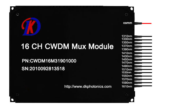
16CH CWDM Mux Module
CWDM In comparison with DWDM
Accordingly, they’ve got two important characteristics built into systems employing CWDM optical components which permit easier and for that reason also less expensive than in DWDM systems. CWDM is very easy in terms of network design, implementation, and operation. CWDM works together few parameters that want optimization from the user, while DWDM systems require complex calculations of balance of power per channel, which is further complicated when channels are added and removed or when it’s utilized in DWDM networks ring, particularly if systems incorporate optical amplifiers.

CWDM Function
CWDM modules perform two functions. First, they filter the lighting, ensuring only the desired wavelengths are used. Second, they multiplex or demultiplex multiple wavelengths, which are put on just one fiber link. The real difference is in the wavelengths, which might be used. In CWDM space, the 1310-band as well as the 1550-band are broken into smaller bands, each only 20-nm wide. Inside multiplex operation, the multiple wavelength bands are combined onto just one fiber. Within the demultiplex operation, the multiple wavelength bands are separated from one fiber.
Generally, a CWDM network takes two forms. A point-to-point system connects two locations, muxing and demuxing multiple signals for a passing fancy fiber. A loop or multi-point system connects multiple locations, typically using Add/Drop modules.

CWDM Modules Types
CWDM Modules utilize thin-film coating and micro optics package technology. CWDM modules consider two main configurations: CWDM Multiplexer/Demultiplexer (CWDM Demux) modules and CWDM Add/Drop Multiplexer (CWDM OADM) modules.
Mux products will include a few statistics symptoms in a only for having using a one-time fabric. Demux isolate all of the symptoms inside various terminate. Any value reaches an extra wavelength.
CWDM Mux/demux are created to multiplex multiple CWDM channels into One or two fibers. Within a hybrid configuration (mux/demux), multiple transmit and receive signals can be combined onto a single fiber. Each signal is assigned a different wavelength. At each and every end, transmit signals are muxed, while receive signals are demuxed. CWDM Mux/demux can be a flexible plug-and-play network solution, allowing carriers and enterprise companies to cheaply implement examine point or ring based WDM optical networks. CWDM Mux/demux is modular, scalable and it’s perfectly suited to transport PDH, SDH / SONET, ETHERNET services over WWDM, CWDM and DWDM in optical metro edge and access networks.
The most popular configuration of CWDM mux/demux is 2CH, 4CH, 5CH, 8CH, 9CH, 16CH and 18CH CWDM MUX/DEMUX. and also Compact CWDM module, 3 Single fiber or dual fiber connection for CWDM Mux/demux can also be found. These modules passively multiplex the optical signal outputs from 4 or higher electronics, send to them merely one optical fiber and then de-multiplex the signals into separate, distinct signals for input into technology along at the opposite end in the fiber optic link.
More information about CWDM: WDM Products

Monday, October 7, 2013

What is Cladding Power Strippers, Where is the Cladding Power Strippers use?


Cladding Power Strippers: devices which can remove light from a fiber cladding.
Cladding Power Stripper
Where is the Cladding Power Strippers use?
In some situations, it is necessary to remove light from the cladding of an optical fiber. Some examples:
-Sometimes, a single-mode fiber is used as a kind of mode cleaner. The wanted light is transmitted through the fiber core, and any other light, spoiling the beam quality, should be removed. In many cases, a polymer coating around the fiber cladding can serve as a Cladding Power Stripper. For that purpose, the refractive index of the coating should be slightly above that of the cladding, so that light can easily be transmitted from the cladding into the coating and then radiated into the ambient air by scattering at irregularities. (Alternatively, the coating may absorb the light.)
-In a high-power fiber amplifier made from a double-clad fiber, residual (unabsorbed) pump light (at the fiber end opposite to the pump end) may have to be removed from the pump cladding (inner cladding) in order to prevent it either from accompanying the amplified signal or from getting to the signal source. A special Cladding Power Stripper may be used for that purpose.
-When pump light is launched into a double-clad fiber (for example, from free space), some of the optical power may get into the outer cladding around the pump cladding. It may propagate in that outer cladding up to a location where the fiber has a polymer coating, and then destroy that coating via excessive heating. That problem may be avoided with a cladding stripper which attenuates light in the outer cladding, but not in the pump cladding.
Cladding Power Stripper for use in high-power fiber lasers and amplifiers need to be able to handle substantial optical powers. It needs to be ensured that these powers are absorbed in a sufficiently widespread region, and that the generated heat can be removed safely, without damaging the mode stripper or any surrounding parts.